KEPCO DIN KIT FCP-10 (P) User Manual
Kepco
©2000, KEPCO, INC
1
Data subject to change without notice
228-1368 (REV 3)
I N S T R U C T I O N M A N U A L
KIT
KEPCO
KEPCO, INC. " 131-38 SANFORD AVENUE " FLUSHING, NY. 11352 U.S.A. " TEL (718) 461-7000 " FAX (718) 767-1102
http://www.kepcopower.com " email: [email protected]
An ISO 9001 Company.
DIN FMP/FCP
-3P, -10P
DIN-RAIL MOUNTING KIT
FOR SERIES FMP/FCP 3W, 10W
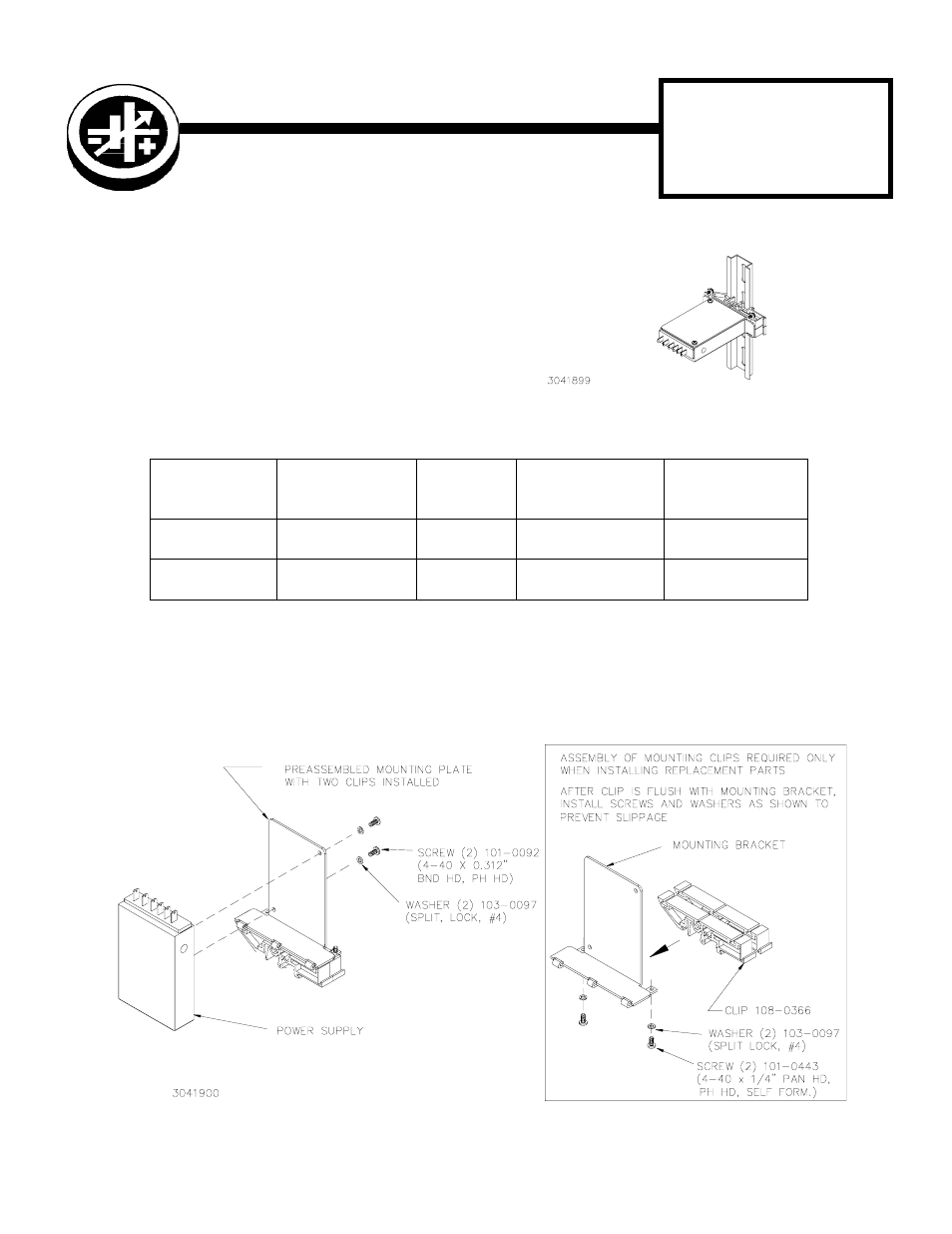
DESCRIPTION. Kepco Kits, Models DIN FMP/FCP
-3P and -10P each contain a preassembled mounting
bracket with two mounting clips and associated hard-
ware used to install FMP and FCP Series power sup-
plies on a DIN rail. The -3 suffix is for the 3 Watt
Series, the -10 suffix is for the 10 Watt Series. The “P”
suffix is for mounting the power supply perpendicular
to the DIN rail as shown in Figure 1. Outline dimen-
sions are shown in Figure 4.
INSTALLATION
1. INSTALL MOUNTING BRACKET. Attach the mounting bracket to the power supply using hardware sup-
plied (see Figure 2).
2. INSTALL POWER SUPPLY ON DIN RAIL. To mount the power supply on the rail insert one end of both
clips under one edge of the rail, then snap the other end of the two clips into place (see Figure 3A).
TABLE 1. COMPONENTS SUPPLIED
KIT
MODEL NO.
MOUNTING
BRACKET
PART NO.
CLIP (QTY 2)
PART NO.
SCREW (QTY 2)
PART NO.
WASHER (QTY 2)
PART NO.
DIN FMP/FCP-3P
128-2052
108-0366
101-0092
(4-40 X 0.312 BHPH)
103-0097
(NO. 4, SPLIT, LOCK)
DIN FMP/FCP-10P
128-1988
108-0366
101-0092
(4-40 X 0.312 BHPH)
103-0097
(NO. 4, SPLIT, LOCK)
FIGURE 2. INSTALLING MOUNTING PLATE ON POWER SUPPLY
FIGURE 1. P SUFFIX ORIENTATION