Checkout procedure, Figure 2. rj45 to db9 adapter wiring, Table 2. rj45 to db9 adapter wire functions – KEPCO BIT 4886 Quick Start Guide User Manual
Page 2: Iii — operation
2
228-1693 REV 1
120612
KEPCO, INC. " 131-38 SANFORD AVENUE " FLUSHING, NY. 11355 U.S.A. " TEL (718) 461-7000 " FAX (718) 767-1102
http://www.kepcopower.com " email: [email protected]
CHECKOUT PROCEDURE.
1. Connect the BOP-BIT 4886 Interface Card to either:
a) the GPIB bus using a standard GPIB cable
connected to the BIT 4886 24-pin GPIB connector
(J1) or
b) to an external RS-232 controller with a DB9
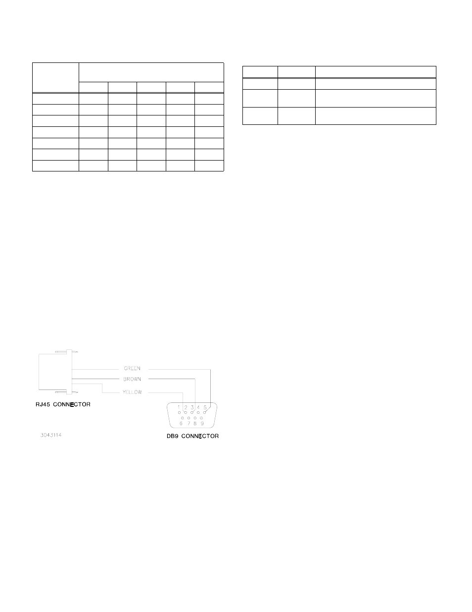
type connector (male pins) by connecting the RJ45
patch cord to the BIT 4886 RS 232 port (J2), then
using the RJ45 to DB9 adapter supplied (see Figure
2) to connect the RJ45 patch cord to the external con-
troller. On the RJ45 patch cord, the 6-pin connector
plugs into the BIT 4886 RS 232 port, and the 8-pin
connector plugs into the RJ45 to DB9 adapter (see
Table 2 and Figure 2).
FIGURE 2. RJ45 TO DB9 ADAPTER WIRING
2. Apply power to BOP power supply. The BOP-BIT
4886 will beep for less than 1 second, then will be
ready for use.
3. Send the *IDN? query via either the GPIB or RS 232
port.
Assuming the BIT 4886 card is installed in a BOP 72-6
as an example, verify that the unit responds with
KEPCO,BIT488-6 72-6,A38621 11/10/98,1.81-1.81.
If the unit responds with KEPCO,BIT488-6 200-
20,A38621 10/01/98,1.81-1.81, it means that the card
was not initialized; refer to Operator Manual to initial-
ize the card. Note that date 10/01/98 is the initial cali-
bration date performed at the factory and indicates the
card has never been calibrated by the user.
4. Send VOLT? Verify that unit responds with 0 (indicat-
ing voltage is set to 0, the power-up condition).
5. Send OUTPUT ON;VOLT MAX. Verify that the BOP
power supply provides maximum output voltage (e.g.,
72V d-c. for BOP 72-6).
6. Send FUNC:MODE CURR. Verify that BOP front panel
current LED lights.
7. Send FUNC:MODE VOLT. Verify that BOP front panel
voltage LED lights.
8. Send *TST? and verify response is 0. This verifies the
bit 4886 microprocessor is operating correctly.
9. With no load connected, send DIAG:TST? and verify
response is 0. CAUTION: This test swings the output
to Volt MAx and Volt Min at full power. If a Load is
connected, damage to the load may occur, or the test
may fail due to the load effect on unit output voltage
III — OPERATION
The BOP can now be controlled via either the RS 232 or
GPIB ports using IEEE 488 and SCPI commands. The
applicable commands and queries are listed in Table 3
and 4, respectively. For a full description of all commands
as well as remote programming information, refer to the
BIT 4886 Operator Manual listed on page 1 of this guide.
25
1
1
0
0
1
26
1
1
0
1
0
27
1
1
0
1
1
28
1
1
1
0
0
29
1
1
1
0
1
30
1
1
1
1
0
31
1
1
1
1
1
NOTE:
0 = CLOSED (ON) (Towards printed circuit board)
1 = OPEN (OFF) (Away from printed circuit board)
TABLE 1. DEVICE ADDRESS SELECTION (CONT)
DECIMAL
ADDRESS
SELECTOR SWITCH S1 SECTION (SIGNAL
LINE)
A5
A4
A3
A2
A1
TABLE 2. RJ45 TO DB9 ADAPTER WIRE FUNCTIONS
Wire
DB9 Pin
Purpose
Green
5
Return for pins 2 and 3.
Brown
3
Carries data from the Kepco power
supply to the controller.
Yellow
2
Carries data from the controller to the
Kepco power supply.