Load connection, remote sensing, Input a-c connections, Isolation from ground – KEPCO ATE (all models) QUICK START GUIDE User Manual
Page 6: Cooling, R. 3.4.3 for
6
228-1757
021012
KEPCO, INC. 131-38 SANFORD AVENUE FLUSHING, NY. 11355 U.S.A. TEL (718) 461-7000 FAX (718) 767-1102
http://www.kepcopower.com email: [email protected]
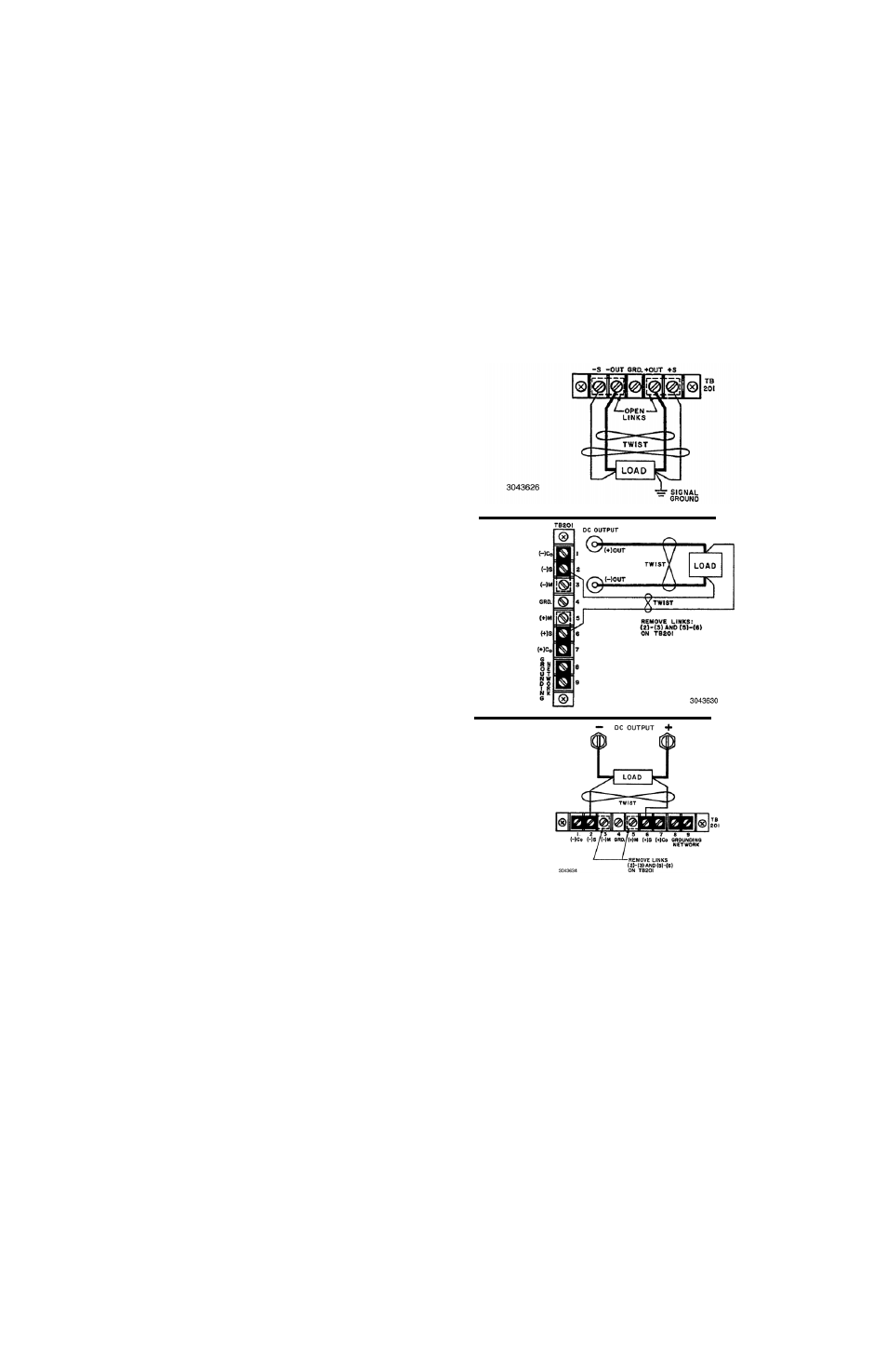
3.4.3. LOAD CONNECTION, REMOTE SENSING. To
avoid excessive output effects at remote loads, remote
error sensing must be used (Kelvin connection). A pair of
wires (twisted to reduce EMI) connected from the sensing
terminals directly to the load will compensate for load wire
voltage drops up to 0.5 volt per wire (refer to Figure 3. 3-
4). Observe polarities: the negative sensing wire must go
to the negative load wire, and the positive sensing wire
goes to the positive load wire.
For large capacitive loads with long wire runs, refer to the
full Operator Manual for techniques used to reduce low
frequency oscillations observed at the load.
3.4.4. INPUT A-C CONNECTIONS. Install the line cord
(supplied) at the rear panel and connect to 115V a-c, 60Hz
(105V to 125V a-c, 50 to 65Hz) mains. Refer to the full
Operator Manual for operation at 104V a-c, 208V a-c or
230V a-c (see PAR. 1.1).A-C Safety Ground.
The power supply is equipped with a 3-wire safety line
cord and polarized plug. The third (green) wire in the line
cord is connected to the chassis and the case of the unit.
If a 2-terminal receptacle in combination with an adapter is
used, it is imperative that the chassis of the power supply
be returned to a-c ground with a separate lead. A ground-
ing terminal is provided (at the rear barrier strip) for this
purpose.
3.4.5. ISOLATION FROM GROUND. The d-c output is
isolated from the a-c source and from any direct connec-
tion to chassis or ground. The maximum output voltage
that can be supported between either output terminals
and ground or chassis is 500V (d-c or peak), plus the
maximum output voltage of the power supply. Either side
of the output may be grounded.
The common mode current (leakage from output to
ground) Is less than 5
µ
A (rms) or 50
µ
A (p-p) at 115V a-c
power input, 60 Hz. To avoid common mode current from
affecting the ATE output, the system (including the pro-
gramming device, if used, load, and ATE) must have a
single connection to ground (earth ground). The d-c
ground wire must be rated for the nominal output current
of the ATE (e.g, for ATE 6-10M, use rating of 10A).
Multiple signal grounds in the system may cause “ground-
loop” problems, since noise signals develop across the
impedances between the multiple ground points. The
exact physical location of the “best” single ground point
must be carefully selected for minimum ripple/noise out-
put.
NOTE: A resistor/capacitor network is connected from the
negative output terminal to the metal chassis of the power
supply. If the internal signal ground is not desired, the con-
nection to the chassis can be opened (see full Operator
Manual).
FIGURE 4. REMOTE SENSING
3.5. COOLING. The components in the ATE power
supply rely on forced air cooling. SIDE PANEL OPEN-
INGS AND THE TOP OF THE CASE MUST BE KEPT
CLEAR FROM ALL OBSTRUCTIONS TO ENSURE AIR
CIRCULATION. Periodic cleaning of the interior of the
power supply is recommended. If the ATE is rack-
mounted or installed into confined spaces, care must be
taken that the ambient temperature (the temperature
immediately surrounding the power supply) does not rise
above 65°C (~149°F).
3/4 Rack
500W,
Full Rack
1000W
1/4 Rack
50W, 100W
1/2 Rack
500W