Connections, Load connection, general, Load connection, local sensing – KEPCO ATE (all models) QUICK START GUIDE User Manual
Page 4
4
228-1757
021012
KEPCO, INC. 131-38 SANFORD AVENUE FLUSHING, NY. 11355 U.S.A. TEL (718) 461-7000 FAX (718) 767-1102
http://www.kepcopower.com email: [email protected]
3.4. CONNECTIONS. Connections are made using
the rear panel terminations (see Figure 3).
3.4.1. LOAD CONNECTION, GENERAL. Connect the
load between –OUT and +OUT output power terminals at
the rear panel (see Figure 3. Sense connections are
required, either local or remote, must be used; other-
wise the unit will not operate.
See PAR. 3.4.2 for local sensing, see PAR. 3.4.3 for
remote sensing. Refer to the full Operator Manual (see
PAR. 1.1) if step changes in the load are expected if, for
example, the load is rapidly changing in value, or if the
power supply is programmed with step functions (square
wave, pulse, etc.) and maximum dynamic performance is
expected. If so, set the unit to “fast” mode by referring to
the full Operator Manual (see PAR. 1.1). Note that ripple
in “fast” mode will be higher than for the default “slow”
mode.
Terminals on the programming connector at the rear panel
and on the barrier strip (TB201) permit maximum flexibility
in power supply/load interface techniques. The program-
ming connector supplied has been pre-wired with jumpers
configured for front panel (local) control of output voltage,
output current and VP crowbar level with the power supply
operating in the “slow” mode.
The rear programming connector MUST be installed for
power supply to operate.
To configure the programming connector to allow remote
programming of the power supply, “fast mode,” or to use a
user-configured unwired PC 12 programming connector
(or to modify the programming connector supplied), refer
to the full Operator Manual (see PAR. 1.1). If the program-
ming connector jumper configuration has been altered,
make sure that all wires are properly soldered: loose con-
nections at the programming connector will cause the
power supply to malfunction.
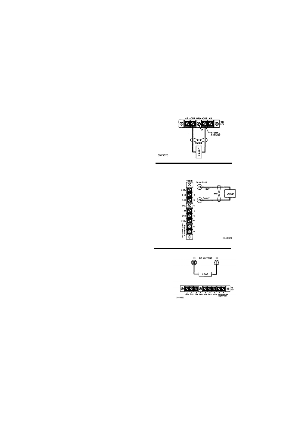
3.4.2. LOAD CONNECTION, LOCAL SENSING. Figure
2 illustrates load connection using local sensing. Refer to
the full Operator Manual for load wire selection guidelines.
The output power leads should be twisted or tied together
to reduce EMI.
FIGURE 2. LOCAL SENSING
3/4 Rack
500W,
Full Rack
1000W
1/2 Rack
250W
1/4 Rack
50W, 100W