Fire-Lite VisorALARM Manager Tool QUICK SETUP GUIDE User Manual
Page 6
VISOR-ALARM Quick Setup Guide
6
Doc. DM381-I
Rev. 1.0
Fig. 7.
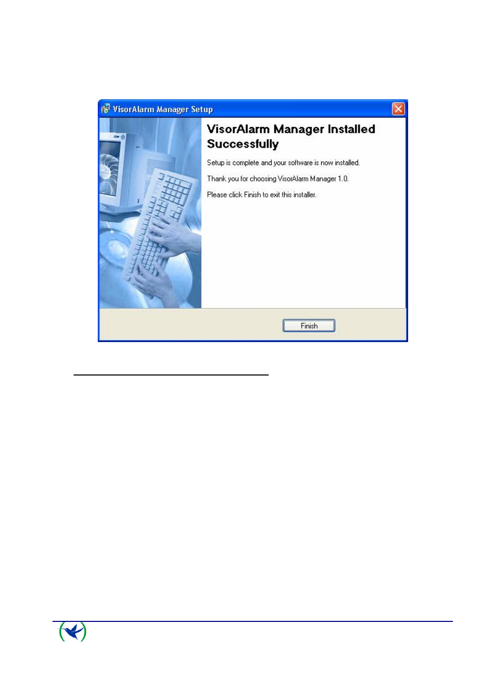
Once the files have been copied, a window appears indicating the installation has been
successfully completed.
Fig. 8.
3.
Connection between PC and VisorALARM
Once the VisorALARM-Manager has been correctly installed, you need to check that
connection between the PC and the VISORALARM can be carried out. The steps to execute
are as follows:
3.1.
Check that both the VisorALARM and the PC are connected to the same Ethernet.
3.2.
Check that the VisorALARM has detected the Ethernet when the Ethernet LAN1
connector LEDs light up. These are located on the rear panel. Likewise, check
that the Windows
TM
in the PC indicates the status of the local area network
connection is connected.
3.3.
The following step is to configure the PC IP address in order to access the
VisorALARM. There are two situations:
•
The VisorALARM is already configured with factory settings. The factory IP
address for the VisorALARM is 192.168.0.200 with mask 255.255.255.0.
Configure the PC network interface with an address pertaining to the
VisorALARM subnet which does not have any other network device, i.e. any
address 192.168.0.X with mask 255.255.255.0, where X is a value between 1
and 254 with the exception of value 200 which is assigned to the
VisorALARM.
The procedure to configure the IP interface in a Windows XP
TM
is as follows:
1.
Access Start\Control Panel\Network Connections.