Section 1: ecc-50da remote amplifier, 1 installation, 1 board layout – Fire-Lite ECC-125DA/E Distributed Audio Amplifiers User Manual
Page 6: Installation, Board layout, Figure 1.1 ecc-50da board layout
6
ECC-50/125DA Instruction Manual — P/N LS10027-000FL-E:B 8/13/2013
Section 1: ECC-50DA Remote Amplifier
1.1 Installation
This section provides information on how to install the ECC-50DA for use with the ECC-50/100
Emergency Command Center.
SW2 on the ECC-50/100’s display board must be set to the UP position if any ECC-50DAs are
installed in the system. Refer to the ECC-50/100 Instruction Manual, P/N LS10001-000FL-E, for
more information. The ECC-50DA must also be enabled in user programming. 70 volt operation
of the ECC-50DA is also set up in user programming. Refer to the programming section of the
ECC-50/100 Instruction Manual, LS10001-000FL-E.
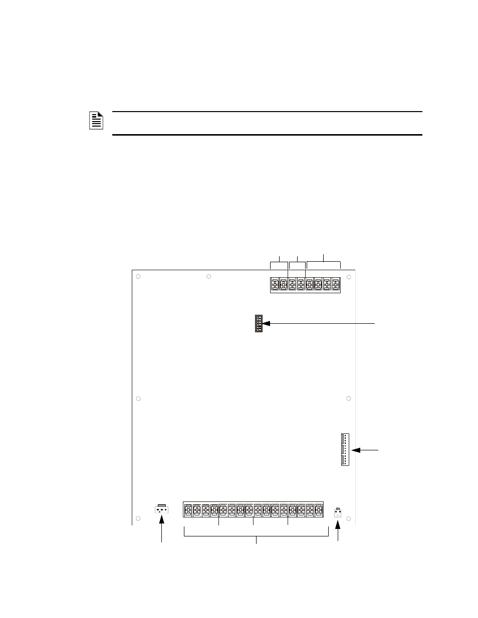
1.1.1 Board Layout
Figure 1.1 shows the location of terminals, dip switch, and circuit expander connection, used in the
installation of the ECC-50DA.
NOTE: The term ECC-50DA is used in this manual to refer to both the ECC-50DA (120 VAC
version) and the ECC-50DAE (240 VAC version) amplifier unless specified.
ON
12
34
5
6
BATTERY
+ –
OUT
–
+
IN
–
+
–
+
A
B
SBUS
CIRCUIT 4
CIRCUIT 3
CIRCUIT 2
CIRCUIT 1
IN
IN
IN
IN
+
+
+
+
–
–
–
–
OUT
OUT
OUT
OUT
+
+
+
+
–
–
–
–
A
U
D
IO
EXP
A
ND
ER
Audio Riser
Out In
Data
Bus
SBUS ID
Dip Switch
Audio
Expander
Connection
Battery
Connector
AC Transformer
Connector
Audio Circuits
Figure 1.1 ECC-50DA Board Layout
ecc-
50da
.w
m
f