A.O. Smith BTH 120 - 250 User Manual
Page 16
16
ERROR CODES
The following Error Codes are external to the controller.
01 Pressure Switch Fail On, should be Off
11 Pressure Switch Fail Off, should be On
02 Ignition Fail after 3 attempts
04 ECO Open
05 Temperature Probe Open
15 Temperature Out of Bounds < 30 degrees
25 Temperature Out of Bounds > 220 degrees
The following Error Codes are internal to the controller.
113 Flame On Should be Off Fail
22 Ignition Relay Fail is On, should be Off
112 Ignition Relay Fail is Off, should be On
101 K2 Fail in K1
102 Main Loop Fail in K2
103 K1 Fail in Main Loop
Gas Valve Power Supply. (*WDPS Watch Dog Power Supply).
106 WDPS Fail to be Off
107 WDPS Fail to be Off
108 WDPS Fail to be On
116 Gas Valve Relay Fail is off, should be On
117 Gas Valve Relay Fail is On, should be Off
Checks The ROM (Read Only Memory).
200 CRC Check Sum Error
Checks The CPU (Central Processing Unit).
201 CPU Instruction Test Error
202 CPU Instruction Test Error
203 CPU Instruction Test Error
Checks the RAM (Random Acess Memory).
205 RAM Test Fail
SW Check to see what the Last State it was in.
ie., Fails if it can from the wrong place
125 State Error
126 State Error
128 State Error
127 State Error
129 State Error
131 State Error
132 State Error
These State Numbers are not used.
230 Executed State 3 (Not Implimented) h.s.
240 Executed State 4 (Not Implimented) h.s
210 Executed State 10 (Not Implimented) h.s.
213 Executed State 13 (Not Implimented) h.s.
214 Executed State 14 (Not Implimented) h.s.
216 Executed State 16 (Not Implimented) h.s.
FAULT CONDITIONS
The controller is set up to provide additional status indicators under Fault
Conditons. The following figures are possible Fault Conditions.
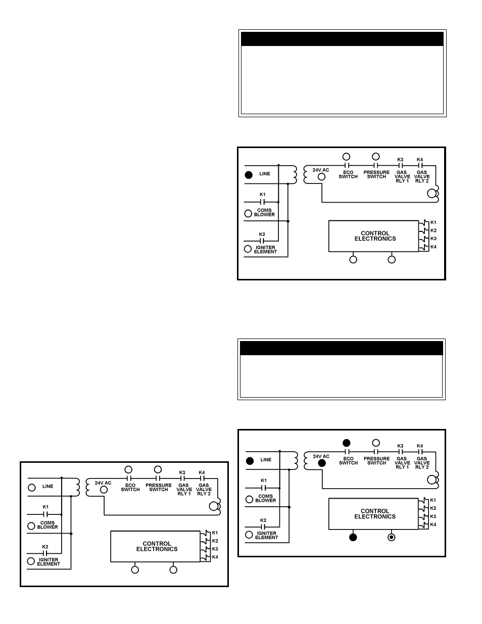
NO INCOMING LINE VOLTAGE (Figure 19)
Line LED Off
NO INCOMING LINE VOLTAGE, Line LED Off
FIGURE 19
Possible Cause
Remedy
1. Transformer wiring problem
1. Repair Wiring
2. Defective Transformer
2. Replace Transformer
3. LED burned out
3. Ignore or replace control
Possible Cause
Remedy
1. No Input Power
1. Apply Power
2. Wiring Disconnected
2. Check all wiring
3. One or more wiring receptacles 3. Reconnect plugs on control,
disconnected from control
confirm all are fully seated
4. LED burned out
4. Ignore or replace control
NO LOW VOLTAGE (Figure 20)
24V AC LED Off
NO LOW VOLTAGE, 24V AC LED Off
FIGURE 20
NOTE: The transformer is of Class II variety and has an internal non-
replaceable fuse. If blown, a problem may exist with the control which is
affecting the transformer. In such cases, the control should be replaced as
well.
TEMPERATURE PROBE FAULT (Figure 21)
Water Temp LED Flashing
TEMPERATURE PROBE FAULT, Water Temp LED Flashing
FIGURE 21
This condition accommodates multiple failure modes. To more accurately
determine the cause of failure, press the pushbutton on the display board.