A.O. Smith BTH 120 - 250 User Manual
Page 14
14
HEATER WIRING
IF ANY OF THE ORIGINAL WIRE AS SUPPLIED WITH THE APPLIANCE
MUST BE REPLACED, IT MUST BE REPLACED WITH 105°C WIRE OR ITS
EQUIVALENT, EXCEPT IN THE BURNER HOUSING. IN THIS CASE USE
200°C WIRE.
THE COMPUTER CONTROL REQUIRES A SOURCE OF STABLE CLEAN
ELECTRICITY FOR PROPER OPERATION. INSTALLING THE HEATER ON
A BRANCH CIRCUIT THAT HAS ELECTRONIC NOISE, IS SUBJECT TO
FLUCTUATIONS IN VOLTAGE LEVEL OR HAS AN APPLIANCE WHICH
GENERATES EMF OF RFI INTERFERENCE CAN CAUSE THE
CONTROLLER TO MALFUNCTION. A HIGH QUALITY POWER
CONDITIONER MUST BE INSTALLED IF THE ABOVE CONDITIONS EXIST.
MALFUNCTIONS CAUSED BY A POOR ELECTRICAL SUPPLY ARE NOT
COVERED UNDER YOUR WARRANTY.
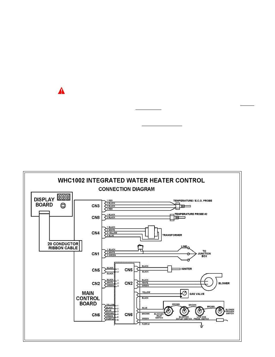
The controller is wired to the heater as shown in figures 16 & 17. The
model and rating plate provides the electrical information needed to
size the complete heater branch supply.
All electrical work must be installed in accordance with the National
Electrical Code and local requirements.
When installed, the appliance must be electrically grounded in
accordance with local codes or, in the absence of local codes, with
the National Electrical Code, ANSI/NFPA 70.
DO NOT ENERGIZE THE BRANCH CIRCUIT BEFORE THE HEATER TANK
IS FILLED WITH WATER.
NOTE: This controller is Polarity Sensitive. If the Hot and Neutral Supply
Voltage is reversed, the controller will not sense flame. Verify polarity
before connecting the unit.
WATER LINE CONNECTIONS
This manual provides detailed installation diagrams (see back section of
this manual) for typical methods of application for the water heaters.
The water heater may be installed by itself, or with a separate storage
tank. When used with a separate storage tank, the circulation may be
either by gravity or by means of circulating pump. When a circulating pump
is used, it is important to note that the flow rate should be slow so that there
will be a minimum of turbulence inside the heater.
CLOSED SYSTEM
CAUTION
A closed system will exist if a check valve (without bypass), pressure
reducing valve (without bypass), or a water meter (without bypass) is
installed in the cold water line between the water heater and street main
(or well).
Excessive pressure may develop causing premature tank failure or
intermittent relief valve operation. This type of failure is not covered by the
limited warranty. An expansion tank or a similar device may be required in
the inlet supply line between the appliance and the meter or valve to
compensate for the thermal expansion of water under supply pressure.
If a water heater is installed in a closed water system, check local codes
or contact the water supplier or local plumbing inspector on how to control
this situation.
FIGURE 16
BSR BOARD (BTH - 250 ONLY)