0 inst allation – Detcon 440 User Manual
Page 8
4.0 Inst allation
4.1 Mounting and Cable Penetrations
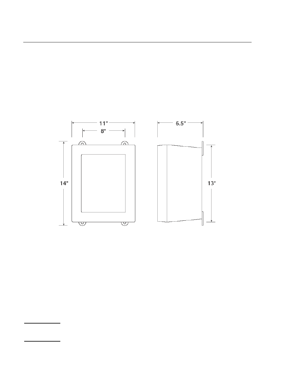
Securely mount the Model 440 RD enclosure per the mounting dimensions provided in Fig. 1.
Provide for suitable conduit/cable entries in the bottom of the enclosure. Keep AC power separate from
DC signals in conduit connections and runs.
Mounting Holes 5/16 Dia.
Figure 2 Mounting Diagram
4.2 Power and I/O Connections
Power and I/O connections are made on the Motherboard PCB, which is mounted on the back of the
enclosure. Plug-in male connector terminal blocks are provided for customer wire terminations. This
connector style provides for quick disconnect convenience during replacement or servicing. (Refer to
Figure 4)
4.2.1 AC Power
Connect 115 or 230 VAC input wiring to the terminals labeled “AC IN” in Figure 3 & Figure 4.
4.2.2 DC Power
For optional DC power input, connect 11.5 – 30VDC to the terminals labeled “DC IN” in Figure 3 &
Figure 4. This input can be used for primary power or back-up power in the event of a VAC power failure.
Model 440-RD Operator Manual
Rev. 1.0.2
Page 4 of 14