2 dc power, 3 serial connection from the model 840 controller, Figure 3 power input schematic – Detcon 840-RD User Manual
Page 9
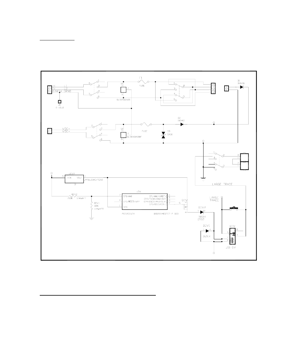
4.2.2 DC Power
For optional DC power input, connect 11.5-30 VDC to the terminals labeled J8 “DC IN” in Figure 3 &
Figure 4. This input can be used for primary power or back-up power in the event of a VAC power failure.
115VAC/220VAC
External
VDC
Input
VDC ON/OFF
VIN
MOTHER BOARD POWER INPUT
External
VAC
Input
J8
+
-
J2
SW4
SW1
VAC ON/OFF
F2
BATTERY
RESTORE
VSS
VIN
SW3
BATTERY
ON/OFF
SWOV
BATT2
BATT1
DC POWER
SUPPLY
TO
FROM
VSS
VIN
SW2
PS1
PS2
Figure 3 Power Input Schematic
4.2.3 Serial connection from the Model 840 Controller
The serial connection from the Model 840 Controller should be terminated at J10 the RS-485 input terminal
of the Model 840 Motherboard, see Figure 4. If applicable, the shield wire should be terminated at the RS-
485 connector labeled JP1 “SHLD TO GND on the motherboard PCB.
Model 840-RD Operator Manual
Rev. 0
Page 5 of 14
- 12B (16 pages)
- FL-10 (7 pages)
- 10C Facilities (18 pages)
- 10C (29 pages)
- 10B (10 pages)
- 1212-N4X (9 pages)
- 812-N4X (9 pages)
- 1212B (5 pages)
- 612B (5 pages)
- 1610-N4X (28 pages)
- 1010-N4X (14 pages)
- 610-N4X (12 pages)
- 1610-N1 (4 pages)
- 810-N1-24VDC (10 pages)
- 410-N1-24VDC (4 pages)
- MCX-32-N1P (55 pages)
- RD-64X-N4X (41 pages)
- 880RA-N4X (36 pages)
- 880RA-N4X (23 pages)
- 880A-N1R (45 pages)
- 880A-N4X (43 pages)
- 880A-N4X (50 pages)
- X40-08-N4X (70 pages)
- 240 (33 pages)
- SW-AV1-N4 (12 pages)
- SW-AV2-DV1 (12 pages)
- A1V1 (9 pages)
- RXT-300 (47 pages)
- RXT-320 (31 pages)
- CXT-N4X (28 pages)
- SW-HMI-32-N4X (24 pages)
- SW-V1-DV2 (11 pages)
- SW-AV1-DV1 (14 pages)
- SW-AV2-DV2 (12 pages)
- SW-AV1-DV2 (12 pages)
- SmartWireless CX (33 pages)
- SmartWireless CXT (49 pages)
- CX-IR (38 pages)
- CX-DM (44 pages)
- CXT-IR (48 pages)
- CXT-DM (56 pages)
- P-1000 (28 pages)
- 1000 (32 pages)
- 1000_CO2 (32 pages)
- 1000_H2S (34 pages)