0 system operation, Figure 1 system operational diagram, 0 syst em operation – Detcon 840-RD User Manual
Page 6: Model 840-rd gas detection/alarm system
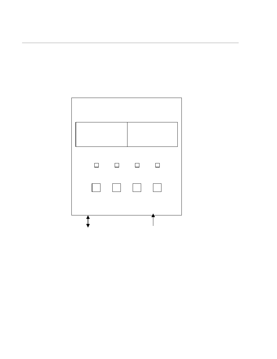
2.0 Syst em Operation
The Model 840-RD receives the data for remote display from the host Model 840 Controller. The system
displays current status information on it’s LCD display, which includes the gas channel #,current reading,
gas type, and alarm LED status. The 840-RD must be configured to exactly match the host 840 controller
for proper operation.
PROG
↑ ↓
ENTER
ALM 1 ALM 2 ALM 3 FAULT
CH1 99 PPM CL2 CH5 99 PPM CL2
CH2 99 PPM CL2 CH6 99 PPM CL2
CH3 99 PPM CL2 CH7 99 PPM CL2
CH4 99 PPM CL2 CH8 99 PPM CL2
Input Power
115/230 VAC
11.5-30 VDC
MODEL 840-RD
Gas Detection/Alarm System
RS- 485 Output
to Master
Device
Figure 1 System Operational Diagram
Model 840-RD Operator Manual
Rev. 0
Page 2 of 14
See also other documents in the category Detcon Equipment:
- 12B (16 pages)
- FL-10 (7 pages)
- 10C Facilities (18 pages)
- 10C (29 pages)
- 10B (10 pages)
- 1212-N4X (9 pages)
- 812-N4X (9 pages)
- 1212B (5 pages)
- 612B (5 pages)
- 1610-N4X (28 pages)
- 1010-N4X (14 pages)
- 610-N4X (12 pages)
- 1610-N1 (4 pages)
- 810-N1-24VDC (10 pages)
- 410-N1-24VDC (4 pages)
- MCX-32-N1P (55 pages)
- RD-64X-N4X (41 pages)
- 880RA-N4X (23 pages)
- 880RA-N4X (36 pages)
- 880A-N1R (45 pages)
- 880A-N4X (50 pages)
- 880A-N4X (43 pages)
- X40-08-N4X (70 pages)
- 240 (33 pages)
- SW-AV1-N4 (12 pages)
- SW-AV2-DV1 (12 pages)
- A1V1 (9 pages)
- RXT-300 (47 pages)
- RXT-320 (31 pages)
- CXT-N4X (28 pages)
- SW-HMI-32-N4X (24 pages)
- SW-V1-DV2 (11 pages)
- SW-AV1-DV1 (14 pages)
- SW-AV2-DV2 (12 pages)
- SW-AV1-DV2 (12 pages)
- SmartWireless CX (33 pages)
- SmartWireless CXT (49 pages)
- CX-IR (38 pages)
- CX-DM (44 pages)
- CXT-IR (48 pages)
- CXT-DM (56 pages)
- P-1000 (28 pages)
- 1000 (32 pages)
- 1000_CO2 (32 pages)
- 1000_H2S (34 pages)