3 main display functions, 4 user-interface menu functions, Figure 8 front panel user interface – Detcon 840-RD User Manual
Page 14
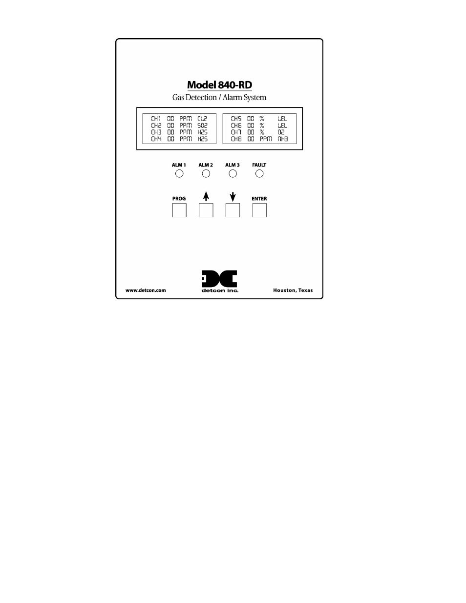
Figure 8 Front Panel User Interface
NOTE: The Remote Display automatically times out of Menu Mode and returns to the Main Display after
1 minute of inactivity. While in Menu Mode there are no updates to gas readings.
6.3 Main Display Functions
The Main Display is a 1¼”x 6” backlit LCD which has 4 lines by 40 characters. In normal operation “CH
# = XX ppm GAS” will be displayed. If any channel is in any gas alarm condition, the “CH#” will
change to “ALM”. If any gas channels are in Fault, they will display “CH # = IN FAULT”. If any
channels are in CAL MODE, they will display as “CH # = In Cal”. If any channels are not communicating
with sensors set up as serial input sensors, then they will display as “CH # = NO COMM”.
NOTE: The LCD has a backlight that will automatically turn off after 30 seconds of inactivity. The LCD
backlight will come on automatically as soon as any function key is pressed. This is a feature designed to
save on power.
6.4 User-Interface Menu Functions
The User-Interface is conducted via the Model 840-RD Front Plate shown above in Figure 8. The Menu
Flow Chart is shown below in Figure 9 and is navigated using the function keys described above. User-
Interface menu activity is conducted via the 1”x5” LCD and the four function keys. There are also four
LED indicators on the front panel that show alarm and fault relay status. The LED’s represent ALM 1
(green), ALM 2 (amber), ALM 3 (red) and FAULT (blue). There are 13 Main Menu entries and their
functional descriptions are discussed below.
Model 840-RD Operator Manual
Rev. 0
Page 10 of 14