Menu flow chart, 1 set # of channels, 2 set channel range – Detcon 840-RD User Manual
Page 15: Figure 9 menu flow chart
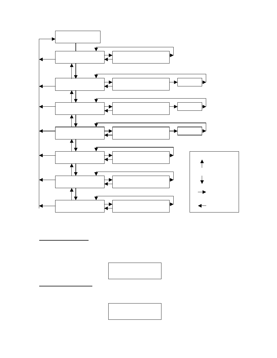
Menu Flow Chart
Figure 9 Menu Flow Chart
6.4.1 Set # of Channels
This menu entry allows the selection of the number of active channels. NOTE: the number of activated
channels can be less than (but not greater than) the controller’s maximum input capacity. It should match
the number of sensors you are hooking up to the controller. The menu appears as:
NORMAL
OPERATION
MAIN MENU:
SET CHANNEL RANGE
SET CHANNEL RANGE
CHX = #####
CH1 … X
MAIN MENU:
SET CHANNEL
TYPE
SET CHANNEL TYPE
CHX = XXXXXXX
CH1 … X
MAIN MENU:
SET CHANNEL ALARMS
SET CHANNEL ALARMS
CHX = ##### ASC/DEC
CH1 … X
MAIN MENU:
SET DATE & TIME
SET DATE AND TIME
MM/DD/YY HH:MM:SS
MAIN MENU:
VIEW TWA &
PEAK
01/02/04 1200 - 1300
TWA #### PK #####
MAIN MENU:
VIEW ALARM RECS
ALM: MM/DD/YY
CHX- A1 ON HH:MM:SS
MAIN MENU:
SET # OF CHANNELS
SET # OF CNHANNELS X
KEY:
Up Arrow
Down Arrow
Enter
PROG
Set # of Channels:
8
6.4.2 Set Channel Range
This menu entry allows the selection of the Channel Range for each gas channel input. This is a scrolling
list from 1.00 up to 10,000 and covers all of the Detcon gas sensor range possibilities. This menu appears
as:
Set Channel Range:
CH1 = XX.X
NOTE: If the range is changed, the alarm levels will have to be reset!
Model 840-RD Operator Manual
Rev. 0
Page 11 of 14