Fig. #2, 11 f, Motherboard schematic diagram – Detcon 110A-FB User Manual
Page 5: Ault, Ircuit
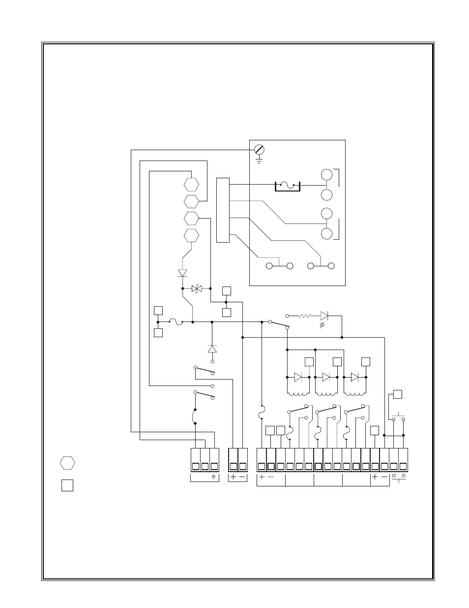
slow blow fuse mounted on the power supply protects against excessive line power (117 VAC). Excessive
DC current is protected by a 1 amp micro-fuse located on the motherboard (see figures #1 and #2).
1.11 F
AULT
C
IRCUIT
F
UNCTIONS
Model 110A-FB digital controls feature fail-safe supervisory circuits designed to assure maximum reliabili-
ty in system performance. The fault circuits supervise all field wiring between remote mounted sensor
assemblies as well as supervise critical internal power supplies. Field wiring between sensors and control
Detcon Model 110A-FB Gas Detection System PG.5
C
NO
FAULT
LOW
HIGH
REMOTE
RESET
SENSOR
VDC
IN
L1 L2
VAC
IN
F3
5A
NC
C
NO
NC
C
NO
NC
4-20MA
3
2
1
4
5 K1
D1
3
2
1
4
5 K2
D2
3
2
1
4
5 K3
D3
5
7
9
MA
F4
5A
F5
5A
6
12
11
F2
1/2A
SW3
RESET
8
SW2
R1
1K
ALARM
DISABLE
RED
CR1
F1
JUMP
SW1
POWER
D4
4001
L1 IN
L2 IN
COM
+DC OUT
PLUG
RIBBON CONNECTOR
ORANGE CONNECTOR
POWER SUPPLY
1 AMP
SLOW
BLOW
1
3
2
4
+ OUT
+S
- OUT
-S
1
2
D5
4001
3
4
1A
F6
+DC
COM
D6
SA30CA
T
ransf
or
mer
F3
5A
F
ault
Lo
w
High
Sensor P
o
w
er
Fig. #2
Motherboard Schematic Diagram