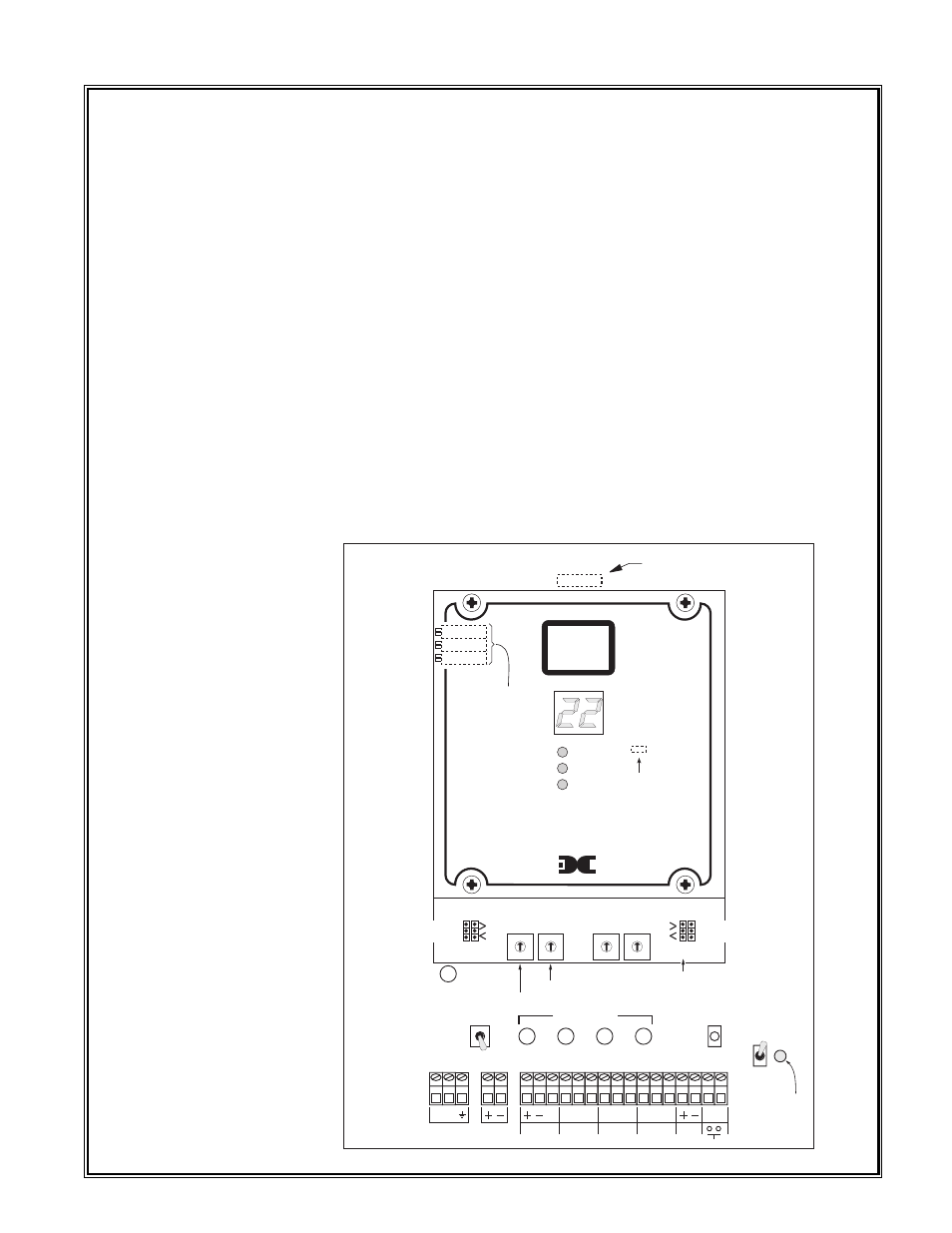
Fig. #1, Operating controls & terminals, Detcon model 110a-fb gas detection system pg.3 – Detcon 110A-FB User Manual
Page 3
1.1 D
ESCRIPTION
Detcon Model 110A-FB is a single channel gas detection system, designed to supervise and display the sta-
tus of remote sensor assemblies that monitor ambient air for a variety of toxic and combustible gases. The
digital controls are compatible with a linear 4-20 madc input signal. The front panel features a direct read-
ing 2 digit display of the concentration of gas and 3 alarm functions that are status displayed via light emit-
ting diodes.
The assembly is enclosed in a NEMA 4X molded fiberglass case with a hinged, gasketed door and is
designed for surface mounting in both indoor and outdoor locations. A Plexiglas view window is mounted
in the door. The NEMA 4X rating is, by definition, raintight and therefore, suitable for outdoor location in
electrically non-hazardous environments. The system is powered by AC line power and/or 24 VDC unless
otherwise specified at time of order.
The control enclosure includes, as standard operating controls (see figure #1); a power on/off switch, an
alarm reset switch, an alarm disable switch with LED indicator, AC line power fuse, DC power fuse, sen-
sor power loop fuse, and alarm output fuses (5A) for Fault, Low and High alarm dry contacts. Discreet
output terminal strips located on the controller mother board are provided for AC power in, DC power in,
sensor terminations, 4-20 madc output for remote recording devices, remote reset and Form C dry contacts
(Common, NO and NC). Contacts are provided for 3 alarms; High, Low and Fault and are rated 8 amp @
117 VAC / 5 amp @ 30 VDC. Additional controls include latching / non-latching alarms, alarm firing
direction, and alarm set dip switches.
Detcon Model 110A-FB Gas Detection System PG.3
JP3
HIGH
LOW
FAULT
detcon inc.
T
E
X
A
S
H O U S T O N
MODEL 110A-FB
ppm / %
SPECIFIC
GAS
MONITOR
HIGH
ALARM
SET
012
3
4
567
89
012
3
4
567
89
012
3
4
567
89
012
3
4
567
89
LOW
ALARM
SET
MOST SIGNIFICANT DIGIT
LEAST SIGNIFICANT DIGIT
MSD
LSD
HIGH
ALARM
LOW
ALARM
NON-LATCH
ALARM FIRING DIRECTION
ASCENDING >; DECENDING <
ALARM
RESET
ALARM
DISABLE
ALARM
ABLE
L1 L2
117
VAC
IN
AUX 24
VDC IN
SENSOR
C
NC
NO
C
NC
NO
C
NC
NO
MA
FAULT
FAULT
LOW
HIGH
4-20
OUT
RESET
ON
OFF
FLT
5 AMP
LOW
5 AMP
HIGH
5 AMP
PUSH
Sensor
Power
1/2 AMP
DISPLAY ZERO
4-20 MA SPAN
4-20 MA ZERO
FACTORY SET
ALARM
DISABLE
LED
INDICATOR
SW1
SW2
SW3
SW4
JP1
JP2
JP4
SW1
Power
1 Amp slow blow fuse
is mounted on power supply.
LATCH
LATCH
NON-LATCH
Micro Fuses
AUX DC
Fuse
1 AMP
JP5
Power Sense
Bypass Jumper
Fig. #1
Operating
Controls & Terminals