Fig. #5 – Detcon 110A-FB User Manual
Page 10
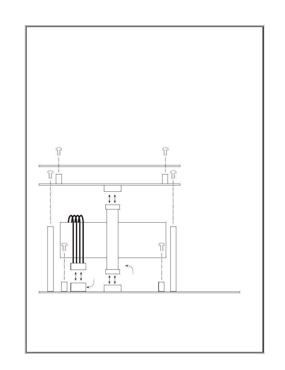
front plate, the control circuit and the ribbon cable (see figure #5). Turn the power switch back on and
measure the VDC output on the power supply on the terminals labeled "+ OUT" and "– OUT" (see fig-
ure #6). If you do not measure between 22 VDC and 28 VDC, replace the power supply as shown in the
breakaway drawing figure #5.
05. If operating by auxiliary DC power, verify that the AUX DC fuse is not open (see figure #1) by remov-
ing it and measuring for continuity. If open, replace with 1 amp micro fuse (see parts list).
ALARMS ARE NOT ACTIVATING
01. If external alarm devices are not working properly, verify that their corresponding fuses are not open
by removing them from the motherboard (see figure #1) and checking for continuity. Fault, Low and
High alarms all use 5 amp micro fuses (see parts list).
MISCELLANEOUS
01. If other problems exist, return the 110A-FB for repair or replacement as discussed in section 1.16 of this
manual or replace damaged components according to the breakaway drawing figure #5. Refer to parts
list for part numbers.
Detcon Model 110A-FB Gas Detection System PG.10
110A-FB Motherboard Assembly
PN5406 - Includes Power Supply
110A-FB Control Circuit Assembly
PN5405
110A-FB Power
Supply Assembly
PN3605
Orange
Connector
6-32 x 5/16
Screw Typ.
Ribbon
Connector
PN9874
110A-FB Front Plate PN8108
6-32 x 5/16
Screw Typ.
6-32 x 5/16
Screw Typ.
Fig. #5
Breakaway Detail