8 wiring diagram – Detcon 971-071170-LRY User Manual
Page 8
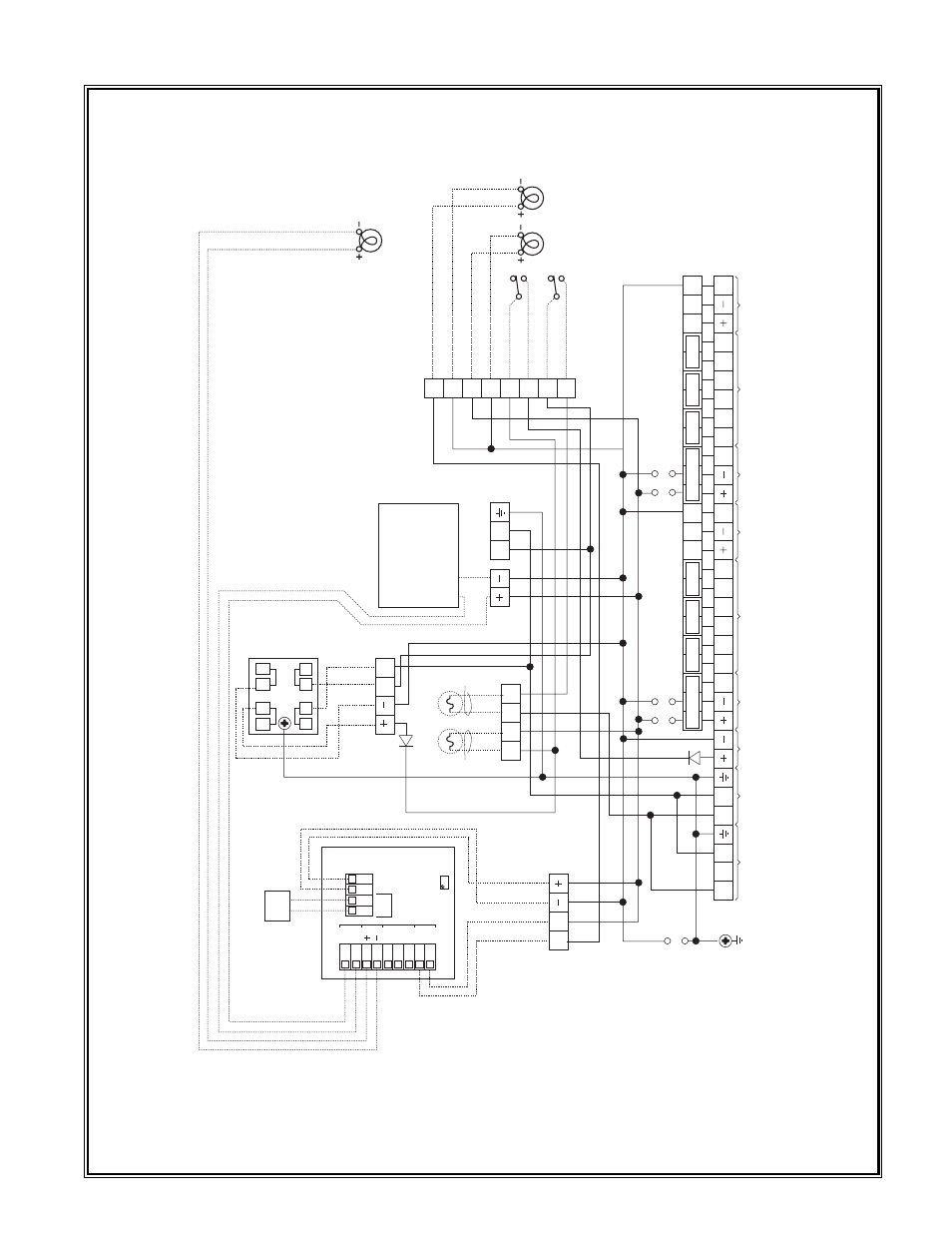
1.8 WIRING DIAGRAM
Shipping address: 2408 Timberloch Place, Bldg. D-1, The Woodlands, Texas 77380
Mailing address: P.O. Box 8067, The Woodlands, Texas 77387-8067
❏ Phone: (281) 367-4100 ❏ Fax: (281) 292-2860
Detcon Model 971-071170-LRY Gas Detection System PG.8
P6
24
VDC IN
Chassis GND
Mounting Screw
P5
11
7
V
AC IN
P4
220 V
AC IN
L2
L1
L2
L1
NEU
F1 DC
Fuse 2A
Power
Switch
Power
Lamp
Flow Fault
Lamp
mA
P7
Sensor #1
P8
Sensor #1
Alarms
C
NO/NC
C
NO/NC
C
NO/NC
P9
Sensor #1
RS-485
SHLD
mA
P10
Sensor #2
P1
1
Sensor #2
Alarms
C
NO/NC
C
NO/NC
C
NO/NC
SHLD
P12
Sensor #2
RS-485
Optional Controller
Fault
Alarm 1
A
larm 2
Fault
Alarm 1
A
larm 2
Optional Controller
D2
1N4001
D1 1N4001
P13
+FFL
–FFL
+PL
–PL
C
NO
C
NO
J1
J2
J3
J4
J5
P15
F2 AC
Fuse 1A
F2
F2
F1
F1
L2
L1
Pump
P1
P2
R
ed 18
BLK
C
NO
Flow
Fault
COM
NO
1
COM
NO
NC
COM
NC
+24V
DC COM
PT1
L2
L1
P3
Power
Supply
3
1
4
2
+O
+S
–S
–O
Red 18
Blk 18
Blk 18
Wht 18
Red 22
Blk 22
Blk 18
Blk 18
Red 18
Blk 18
Blk 22
Red 22
Blk 22
Red 22
Blk 18
Blk 18
Red 18
Red 18
Note: If controllers are hooked directly
to sensors, remove J1 through J4
P14
Optional
Liquid Level
Fault Lamp
Liquid Level
Module
LL
SW
Wire #x22*
Wire #x21*
Wire #x24*
Wire #x23*
Wire #x27*
Wire #x28*
Wire #x26*
Wire #x25*
Blk 22
Red 22
* “x” = Channel Number (1 thru 4)
Wire #x06*
Wire #x07*
Wire #x10*
Wire #x11*
Wire #x00*
Wire #x01*
Wire #x02*
Wire #x03*
Wire #x16*
Wire #x17*
Wire #x18*
Wire #x19*
Wire #x12*
Wire #x13*
Wire #x14*
Wire #x15*
Wire #x20*