Operation, Figure 14 magnetic programming tool, Figure 15 magnetic programming switches – Detcon CXT-IR User Manual
Page 20
Model CXT-IR
3. Operation
The Operator Interface of the Model CXT Series gas sensors is accomplished via two internal magnetic
switches located to either side of the LED display (Figure 15). The two switches, labeled PGM1 and PGM2,
allow for complete calibration and configuration, eliminating the need for area de-classification or the use of
hot permits.
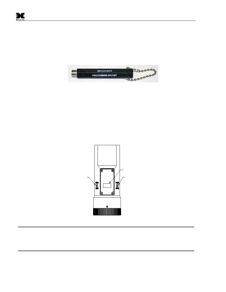
Figure 14 Magnetic Programming Tool
The magnetic programming tool (Figure 14) is used to operate the magnetic switches. Switch action is defined
as momentary contact (a swipe), a 3 second hold, and a 10 second hold. (Hold times are defined as the time
from the point when the arrow prompt appears. Swiping the magnet does not display the prompt.) For
momentary contact use, the programming magnet is briefly held over a switch location, or swiped. For 3
second hold, the programming magnet is held in place over the switch location for three seconds. For 10
second hold, the programming magnet is held in place over the switch location for 10 seconds. The 3 and 10
second holds are generally used to enter calibration/program menus and save new data. The momentary
contact is generally used to move between menu items and to modify set-point values. Arrows (
◄ and ►) are
used on the LED display to indicate when the magnetic switches are activated. The location of PGM1 and
PGM2 are shown in Figure 15.
detcon inc
.
MODEL
CXT-IR
Programming Switch #1
LED Display
Programming Switch #2
Figure 15 Magnetic Programming Switches
NOTE
While in the program mode, if there is no magnetic switch interaction after 4 consecutive
menu scrolls, the sensor will automatically revert to normal operating condition. While
changing values inside menu items, if there is no magnet activity after 3 to 4 seconds the
sensor will revert to the menu scroll. If the sensor is in Bump Test mode, the display will
remain active.
CXT-IR Instruction Manual
Rev. 1.6
Page 16 of 44