1 alarm and fault jumpers, Alarm and fault jumpers, Figure 4 motherboard wiring diagram – Detcon 1610-N4X User Manual
Page 9: Figure 4, 20 out” (+ and –, figure 4, Figure 4). if applicable, term
Model 1610-N4X
A1
C1
C2
A2
A3
C3
C4
A4
A5
C5
A6
C6
C7
A7
A8
C8
C9
A9
A10 C10
A11 C11
C12
A12
A13 C13
C14
A14
A15 C15
A16 C16
Al2-COM
Al2-NC
Al2-NO
FLT-COM
FLT-NC
FLT-NO
4-20 OUT
4-20 IN
--
XM+
XM+
XM+
--
VDC+
VDC+
VDC+
AL1-NO
AL1-NC
Al1-COM
--
485-A
RST
485-S
485-B
--
XM-
XM-
XM-
--
VDC-
VDC-
VDC-
GND
ALM COIL
-
+
RS-485
ALM POWER
L1
N
+
-
N
GND
A(+)
B(-)
Shld
VDC IN
ALM RESET
L1
-
+
VAC IN
P14
P15
P16
P17
P18
P20
N
GND
L1
PS VAC
P13
PS DC
-
+
P12
BRKR
P11
1
2
1
2
1
2
1
2
1
2
3
1
2
3
1
2
1
2
3
4
5
1
2
3
1
2
3
4
5
6
7
8
9
10
11
12
13
14
P11
1
2
3
4
5
6
7
8
9
10
11
12
13
14
JP1-JP15
A
B
C
D
E
F
G
H
I
P12-P26
mA
NC
+
COM
NC
NO
NO
NC
NO
COM
COM
+
ALM
1
OU
T
4-20
FAUL
T
SENS
O
R
ALM2
A1
C1
C2
A2
A3
C3
C4
A4
A5
C5
A6
C6
C7
A7
A8
C8
C9
A9
A10 C10
A11 C11
C12
A12
A13 C13
C14
A14
A15 C15
A16 C16
CH1
CH2-CH116
RS-485
Shield
to Gnd
Earth
Ground
Tie to
Chassis
CH1
CH2-CH116
Typical
Jumpers
D2 6A 50V
D1 6A 50V
P19
JP10
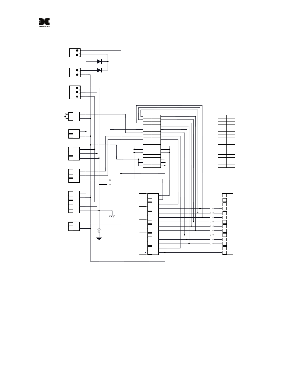
Figure 4 Motherboard Wiring Diagram
2.1 Alarm and Fault Jumpers
A bank of jumpers is provided between each channel for use in setting up alarm and fault schemes. These
jumpers can be installed or removed to create discrete or zoned alarm/fault schemes in conjuncture with the
Model 10 Control Module relay settings. With all of the jumpers installed on the motherboard, the relays on
the Control Modules are placed in parallel with each other. (I.E. All of the Alarm 1 relays are in parallel, all of
the Alarm 2 relays are in parallel, and all of the Fault Relays are in parallel.) In this configuration, the
normally open (“NO”) contacts of the relays would be used to generate an alarm or fault condition, as contact
closure on any Control Module would create continuity between the “COM” contact and the “NO” contact
output for that alarm or fault. A scheme for alarms should be conceived before power is applied to the unit,
and the unit should be set up accordingly. For aid in setting up an appropriate alarm/fault scheme, contact
Detcon Customer Service.
1610-N4X Instruction Manual
Rev. 1.4
Page 5 of 10