Figure 3 mounting of ss enclosure – Detcon 1610-N4X User Manual
Page 8
Model 1610-N4X
ALM 2
ALM 1
FAULT
MODEL 10
ALARM
RESET
TEST
ALM 2
ALM 1
FAULT
MODEL 10
ALARM
RESET
TEST
ALM 2
ALM 1
FAULT
MODEL 10
ALARM
RESET
TEST
ALM 2
ALM 1
FAULT
MODEL 10
ALARM
RESET
TEST
ALM 2
ALM 1
FAULT
MODEL 10
ALARM
RESET
TEST
ALM 2
ALM 1
FAULT
MODEL 10
ALARM
RESET
TEST
ALM 2
ALM 1
FAULT
MODEL 10
ALARM
RESET
TEST
ALM 2
ALM 1
FAULT
MODEL 10
ALARM
RESET
TEST
ALM 2
ALM 1
FAULT
MODEL 10
ALARM
RESET
TEST
ALM 2
ALM 1
FAULT
MODEL 10
ALARM
RESET
TEST
ALM 2
ALM 1
FAULT
MODEL 10
ALARM
RESET
TEST
ALM 2
ALM 1
FAULT
MODEL 10
ALARM
RESET
TEST
ALM 2
ALM 1
FAULT
MODEL 10
ALARM
RESET
TEST
ALM 2
ALM 1
FAULT
MODEL 10
ALARM
RESET
TEST
ALM 2
ALM 1
FAULT
MODEL 10
ALARM
RESET
TEST
ALM 2
ALM 1
FAULT
MODEL 10
ALARM
RESET
TEST
www.detcon.com
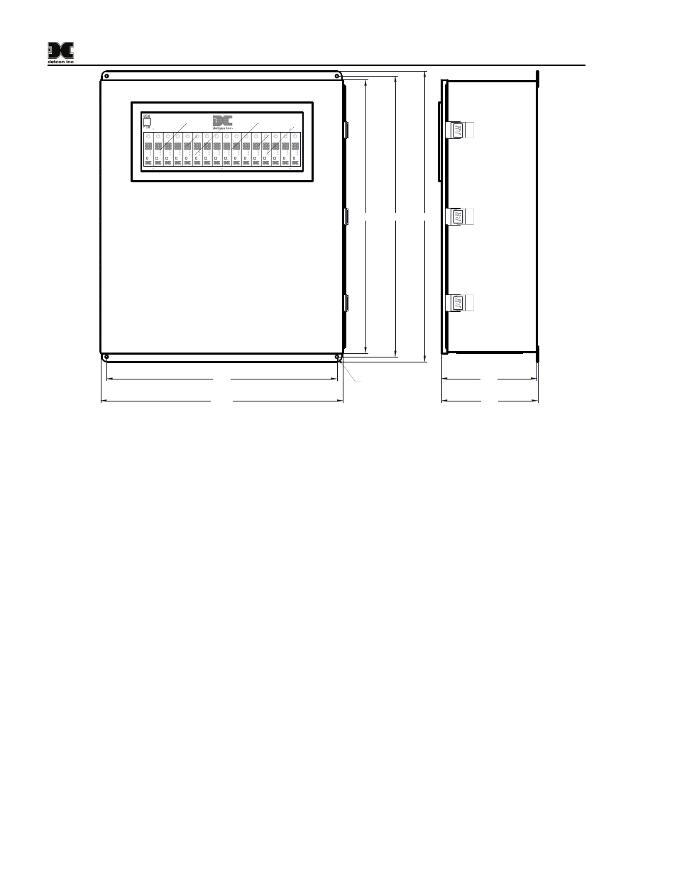
Model 1610-N4X
27.85
28.6
29.6
23.5
24.75
9.75
9.85
Ø0.31
Figure 3 Mounting of SS Enclosure
2. Refer to installation and wiring detail of remote mount sensor assemblies as detailed in the Sensor
Instruction Manual. Terminate field wiring from sensors on the 1610-N4X motherboard. Terminals
are labeled “Sensor” (mA, + and –, Figure 4).
3. If applicable, terminate the discrete 4-20mA outputs to external device(s). Terminals are labeled “4-
4. If applicable, terminate the RS-485 serial output to external device(s). Terminals are labeled “RS-
485” (A+, B–, and Shield, Figure 4). If applicable, terminate RS-485 Shield to Earth Ground via the
jumper tab located to the left of the RS-485 terminals. Place the jumper on the bottom 2 contacts to tie
RS-485 shield to Earth Ground or place the jumper tab on the top two terminals for storage.
5. If applicable a Remote Reset Switch can be utilized by connecting a Momentary, Normally-Open
Switch to P14 (ALM RESET).
6. Earth Ground can be connected to the ground point located in the lower left quadrant of the
motherboard.
7. If applicable, connect a 24VDC source or standby battery to the terminal strip labeled “VDC IN”
(P15+ and –) on the Motherboard (Figure 4).
NOTE: If the unit has the Battery Backup Option installed (1610-N4X-BBU), do not connect an external
power source to P15.
8. Connect 110/220VAC input wiring to the terminals labeled “VAC IN”; P16-1 (L), P16-2 (N), and
P16-GND Ground (Figure 4). The Power Supply will accept input voltages from 100 to 240VAC,
50/60Hz.
1610-N4X Instruction Manual
Rev. 1.4
Page 4 of 10