2 start up, Start up, Figure 5 backplane configuration jumpers – Detcon 1610-N4X User Manual
Page 10
Model 1610-N4X
CH...
CH2
CH14
CH15
JP14
A
B
C
D
E
F
G
H
I
JP...
A
B
C
D
E
F
G
H
I
JP2
A
B
C
D
E
F
G
H
I
JP1
A
B
C
D
E
F
G
H
I
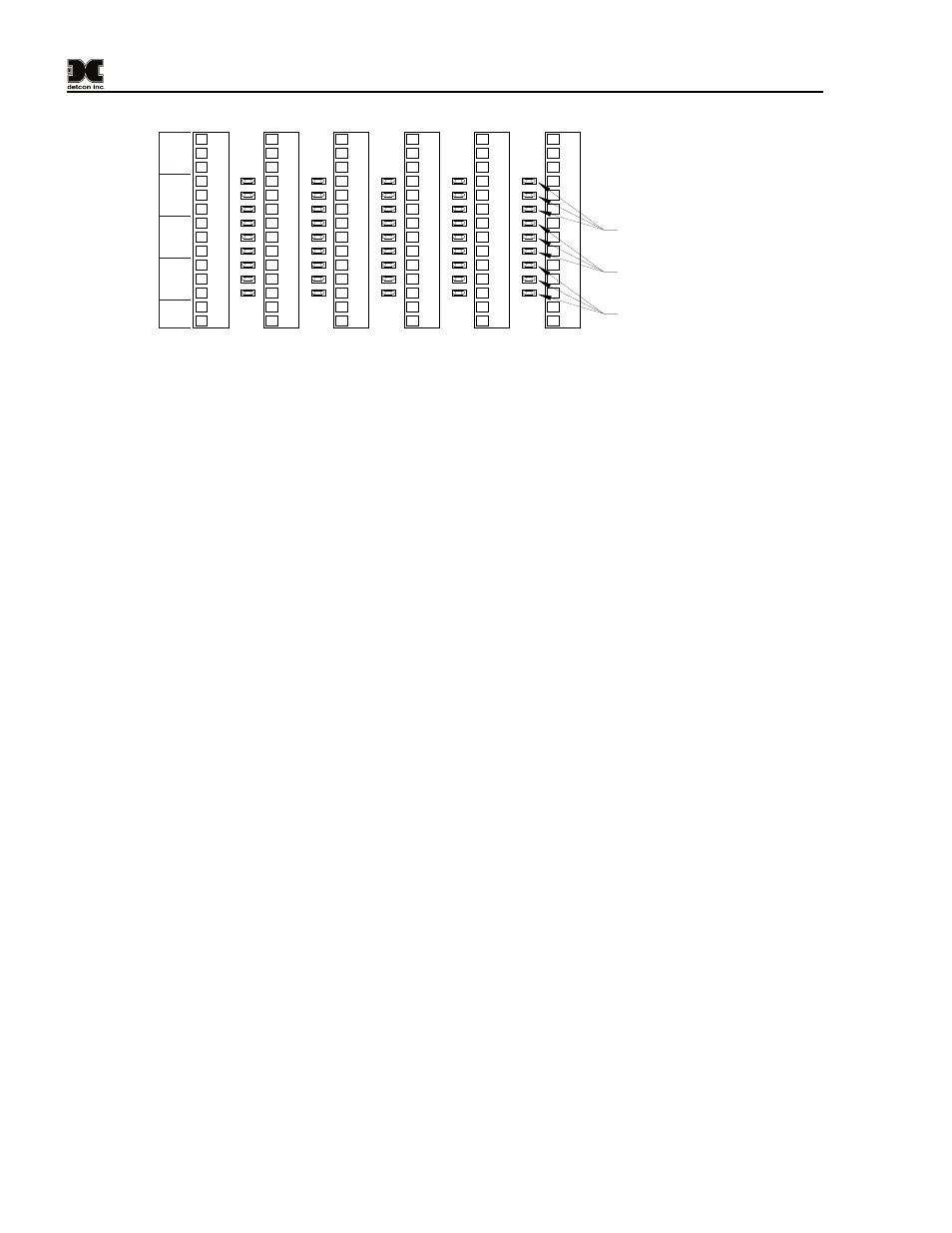
Fault Jumper positions
G, H, and I.
1
2
3
4
5
6
7
9
9
10
11
12
13
14
1
2
3
4
5
6
7
9
9
10
11
12
13
14
1
2
3
4
5
6
7
9
9
10
11
12
13
14
1
2
3
4
5
6
7
9
9
10
11
12
13
14
ALM 1
OUT
4-
20
FAULT
-
NO
+
C
NC
NO
C
SE
NS
OR
ALM2
NC
NO
C
NC
mA
-
+
CH1
1
2
3
4
5
6
7
9
9
10
11
12
13
14
CH16
JP15
A
B
C
D
E
F
G
H
I
1
2
3
4
5
6
7
9
9
10
11
12
13
14
Alarm 1 Jumper positions
D, E, and F.
Alarm 2 Jumper positions
A, B, anc C.
Figure 5 Backplane Configuration Jumpers
2.2 Start Up
Upon completion of all field wiring: Apply power to the 1610-N4X by setting the 5Amp Circuit Breaker (the
Circuit Breaker is also a Power Switch, labeled ‘5Amp’) on the front on the Card Cage. Note that each Model
10 controller digital display illuminates.
NOTE: Varying readings may occur during sensor warm-up. A 10 second alarm delay will occur on
power up. Refer to the applicable Sensor Instruction Manual for additional sensor start-up details.
1610-N4X Instruction Manual
Rev. 1.4
Page 6 of 10