AW Gear Meters Quad-4 User Manual
Quad-4 hall effect pickup, Installation and technical data guide, Rev 07/09
Switch
Output 1
Output 2
0
Flow Direction
Signal 2
1
1x frequency +90 deg phase
2
Flow Direction
2x frequency
3
2x frequency +90 deg phase
4
Flow Direction
4x frequency
5
Both outputs 4x frequency in phase
6
Reserved
7
Forward pulses
Reverse pulses
8
Test: S1 & S2 == 10 Hz (
+/- 20%)
Phase = +90 deg.
9
Test: S1 & S2 == 250 Hz (
+/- 20%
) Phase = -90 deg.
Quad-4 Hall Effect Pickup
Installation and Technical Data Guide
AW Flow Meters - Franksville, WI Phone: (262) 884-9800 Fax: (262) 884-9810
Email: [email protected] www.awcompany.com
Rev 07/09
NOTE: WIRING SHOULD BE INSTALLED BY A QUALIFIED INSTRUMENTATION TECHNICIAN
Pin Number
Wire Color
Signal 2:
2
Green
Signal 1:
4
White
Ground:
5
Black
Supply Voltage:
6
Red
AW Company wiring color code:
Pin Number
Function
1
NC
2
Output 2
3
NC
4
Output 1
5
Ground
6
Supply
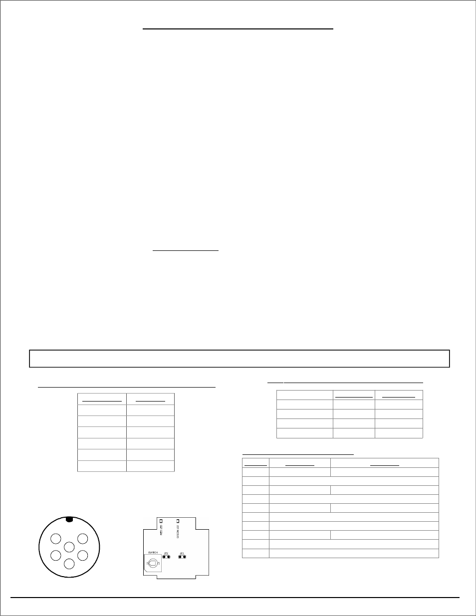
Electrical Connection for Pin Connector
1
2
3
5
6
4
Pinout looking at male
connector on sensor
Quad-4 Operating Modes
Top view of circuit board with
view of LED’s and switch
Installation:
• Ensure that the flowmeter sensor cavity is free of debris prior to installing pickup
• Install flow meter and sensor - CYCLE POWER - or sensor will not function properly!!
• Sensor is equipped with an output test feature for readouts before initial running of your system
TEST FEATURE:
Note: Power must be cycled for new setting to take effect
• Switch setting 8 will cause the pick-up to output a 10 Hz (+/- 20%) Phase = +90 deg pulse output, simulating
low flow conditions without flow through the meter.
• For sinking outputs remove shorting block from JP1 & JP2
For sourcing outputs place shorting block across JP1 & JP2 (factory default)
• Switch setting 9 will cause the pick-up to output a 250 Hz (+/- 20%) Phase = -90 deg pulse output, simulating
medium flow conditions without flow through the meter.
Description:
The Quad-4 Hall Effect Pickup is a microprocessor-based sensors for use with the JV-80/-90KL series of
positive displacement flow meters. The Quad-4 sensor can detect both uni- and bi-directional flow. The
sensors’ mode of operation is determined by an output selection switch located inside the housing. The
Quad-4 detects the rotation of the flow meter gears and emits a frequency signal proportional to flow. The
output signal is a square wave pulse which has a duty cycle of approximately 50%.
Quad-4 signal outputs are protected with a self-resetting fuse. This fuse has a 50mA nominal trip point.
When a trip occurs, turn off power to the sensor and remove output load to reset fuse. The sensor has two
different output configurations: sinking output when jumpers JP1 & JP2 are removed and sourcing when
jumpers JP1 & JP2 are shorting pins.
The Quad-4 sensor circuit board is equipped with a red and green LED. The red LED is a status LED which,
when the sensor is operating properly, will flash once every 4 seconds, a fast flash will indicate a failure of
one or more of the pick-ups. The green LED indicates the pulse of the input signal. Note that signals above
20Hz will look as solid green.
Note: Power must be cycled for new
setting to take effect