AW Gear Meters CAPM-2o User Manual
Capm-2o carrier frequency pickup module, Technical data
AW Gear Meters 8809 Industrial Drive, Franksville, WI 53126 web: www.awgearmeters.com
Tel: 262-884-9800 Fax: 262-884-9810 Email: [email protected]
REV. 12/08 CAPM-2o.DOC
CAPM-2o Carrier Frequency Pickup Module
Installation & Technical Guide
Installation:
•
Ensure that the flow meter sensor cavity is free of debris prior to installation.
•
Screw the CAPM-2o into the flow meter by hand until the sensor nose contacts the bottom of the cavity.
•
Do not screw in harder than hand tight, as a thin metal section is under the sensor nose.
Please heed the following warning:
CAUTION: DO NOT EXCEED 7 NEWTON-METERS FORCE TO SEAT THE SENSOR, THIS IS
EQUIVALENT TO HAND TIGHT. EXCESS FORCE MAY CRUSH THE SENSOR NOSE OR
DAMAGE THE FLOW METER BY FORCING THE METAL SECTION UNDER THE SENSOR INTO
THE MEASURING CHAMBER.
Wiring should be installed by a qualified instrumentation technician.
Some basic installation guidelines are reviewed overleaf.
Description:
The CAPM-2o is a UL & CUL approved, intrinsically safe pickup sensor for use in Class 1, Div. 1
locations. The output signal is a frequency proportional to flow in a square wave voltage form of
approximate amplitude: Supply – 1.5V. The sensor must be installed with an intrinsic safety barrier in
accordance with the guidelines detailed in document # CAP2902 – CAPM INSTALLATION IN
HAZARDOUS AREA
. Recommended barriers such as Pepperl & Fuchs Z787 (12-28V) are available
from AW Flow Meters.
The output is a sourcing open collector transistor (NPN Type).
An NPN sinking type is available and is designated as CAPM-2i.
Technical Data
Supply Voltage: 10 to 30 Volt DC
Supply Current: 20 mA @ 15 Volt, Max 35 mA
Minimum Signal: 0.5 Hz
Signal Output: Square wave, V
High
≈ V
CC
- 1.5V
V
Low
≈ 0V
Duty Cycle:
50%
Frequency Output: Flow dependent, up to 2000 Hz
Load:
>500Ω
Driving Capacity:
10 mA Max
Temperature Range: -60°F to 185°F (-50°C to 85°C)
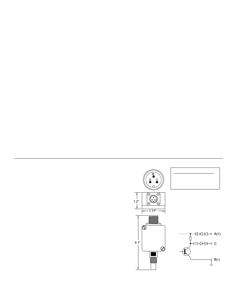
Connections:
A – +10 to 30 Volt DC supply voltage
B – Ground for supply and signals
C – Frequency signal output
Note: If signal does not go to ground, connect
external resistor, 5 K-10 Kohm, between input and
ground of monitoring equipment.
Figure 1
AW Wiring Color Code:
Supply Voltage: Red
Ground: Black
Signal: White