AW Gear Meters HEF User Manual
Hef hall effect pickup, Installation and technical data guide, Rev 06/06
HEF Hall Effect Pickup
Installation and Technical Data Guide
AW Flow Meters - Franksville, WI Phone: (262) 884-9800 Fax: (262) 884-9810
Email: [email protected] www.awflowmeters.com
Rev 06/06
Description:
The HEF is a Hall Effect sensor which is compatible with the Aluminum, 303 Stainless Steel and 316 Stainless
Steel body JV-CG and JV-KG series of flow meters. The sensor detects the rotation of the flow meter’s gears
and emits a frequency signal proportional to flow. The output signal is a square wave pulse which has a duty
cycle of approximately 50%.
HEF signal outputs are protected with a self-resetting fuse. This fuse has a 50mA nominal trip point. When a
trip occurs, turn off power to the sensor and remove output load to reset fuse.
The HEF sensor has two different output configurations: HEF-A or HEF-AA for a sinking output and HEF-B or
HEF-BB for sourcing output.
Installation:
• Ensure that the flowmeter sensor cavity is free of debris prior to installing pickup
• Make sure the sensor mounting screws line up with the mounting holes. If they do not, remove and rotate
the sensor 180°
NOTE: WIRING SHOULD BE INSTALLED BY A QUALIFIED INSTRUMENTATION TECHNICIAN
Pin Number
Wire Color
Supply Voltage:
6
Red
Ground:
5
Black
Signal:
4
White
AW wiring color code:
Pin Number
HEF-A / -AA
HEF-B / -BB
1
NC
NC
2
NC
NC
3
NC
NC
4
Output
Output
5
Ground
Ground
6
Supply
Supply
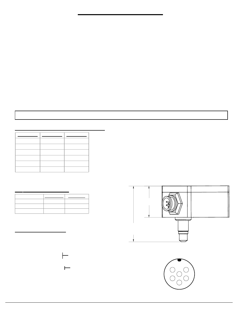
Electrical Connection for Pin Connector
1
2
3
5
6
4
1.19"
HEF-X: (2.12")
HEF-XX: (2.39")
Part number configuration:
HEF sensors can be used wih all Aluminum, 303 Stainless
Steel and 316 Stainless Steel body flow meters
JV-CG 01, 10, 15, 20 & 30
JV-KG 12, 20 & 30
JV-60CG & JV-60KG ONLY
Pinout looking at male connector on sensor
HEF-A, HEF-B
HEF-AA, HEF-BB