Technical data – AW Gear Meters IF Series User Manual
Page 2
AW-Lake Company 8809 Industrial Drive, Franksville, WI 53126 Tel. 800-850-6110 Fax. 262-884-9810
Rev 1/2012
[email protected] www.awgearmeters.com Doc ID: IF Series w/ VTEG Amp.Ind
Version
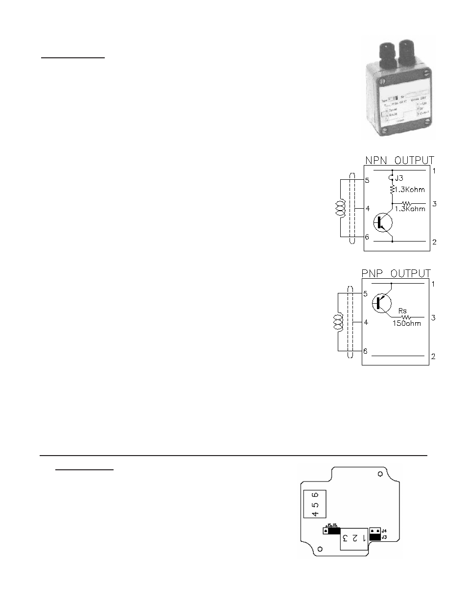
2-Wire
3-Wire active NPN
3-Wire active PNP
3-Wire passive NPN
J3
Off
On
On
Off
J5
Off
Off
On
Off
J6
Off
On
Off
On
Terminal
1, 2
1, 2, 3
1, 2, 3
1, 2, 3
J4
On
Off
Off
Off
Jumper Setting and Terminals
Technical Data
Operating temp:
-20°C to + 80°C
Supply voltage:
U
B
: 7 to 29V/DC
Current consumption: I
R
< 4mA
Output:
Square wave frequency output
Electrical data:
Voltage level NPN/PNP (three-wire connection)
Current level (two-wire connection)
High level: I
High
> 2.2mA
Low level: I
low
< 1.4mA
A) Active output NPN
High level: U
High
> U
B
- 0.6V - (2.6k x I
out
)
Low level: U
Low
> 0.6V + (1.3k x I
out
)
Ω
Ω
C) Active output PNP
High level: U
High
> U
B
- 0.6V - (150 x I
out
)
Low level: U
Low
= cut off
Ω
D) Passive output PNP (OC-output)
High level: U
High
> U
B
- 0.6V - (150 x I
out
)
Low level: U
Low
= cut off
U
B
is the applied voltage at the output. 29V max.
I
max
= 60mA; P
max
on R
s
= 1W; R
s
= 150
Ω
Ω
Input impedance:
< 100
Input:
0.5mV up to 0.5V
Frequency range:
7-3000 Hz according to flowmeter type
Electrical connection:
Terminals 1, 2, 3 for supply voltage, ground & signal outlet
Terminals 4, 5, 6 for shield and inductive pickup
Ω
B) Passive output NPN (OC-output)
High level: U
High
= U
B
Low level: U
Low
< 0.6V + (1.3k x I
out
)
U
B
is the applied voltage at the output. 29V max.
Ω
VIEG Amplifier
VIEG Amplifier
Housing:
Aluminium
IP65 (DIN40050)
L = 64mm; W = 58mm; H = 37mm
two cable glands PG7, plastic