Hef hall effect pickup, Installation and technical data guide, Rev 06/06 – AW Gear Meters HEF User Manual
Page 2: Technical data
HEF Hall Effect Pickup
Installation and Technical Data Guide
AW Flow Meters - Franksville, WI Phone: (262) 884-9800 Fax: (262) 884-9810
Email: [email protected] www.awflowmeters.com
Rev 06/06
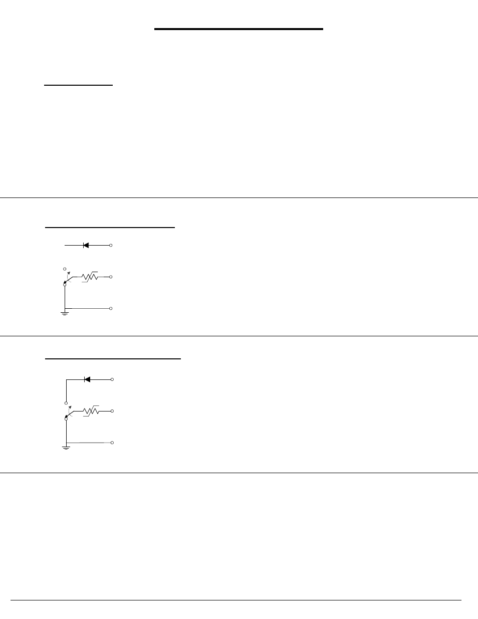
HEF-A / -AA Sinking Output Circuit
~40 Ohm
SUPPLY
OUTPUT
GROUND
Analog
Switch
HEF-B / -BB Sourcing Output Circuit
~40 Ohm
SUPPLY
OUTPUT
GROUND
Analog
Switch
• User may need to add external components to interface to displays
or other instruments
• User must limit output voltage to Supply -1V
• Max current sinking capability: 50mA
• Signal output square wave :
Vhigh = Supply -1V @ no output load
Vlow = 0.1V
• Max sourced output voltage: Supply -0.5V
• Max current sourcing capabilities: 50mA
Supply Voltage:
+10 to 28 Volt DC
Supply Current:
8 mA @ 12 VDC, 12mA @ 24 VDC
Duty Signal:
50% ± 15%
Minimum Signal:
0.5 Hz
Frequency Output:
Flow dependent, up to 2,000 Hz
Driving Capacity:
50 mA Max resistive load
Output Impedance:
~ 40 Ohm - analog switch and self-resetting fuse
Temperature Range:
-40° F to 185° F (-40° C to 85° C)
Technical Data: