Never connect the shield to ground at both ends – AW Gear Meters CAPM-2o User Manual
Page 2
AW Gear Meters 8809 Industrial Drive, Franksville, WI 53126 web: www.awgearmeters.com
Tel: 262-884-9800 Fax: 262-884-9810 Email: [email protected]
REV. 12/08 CAPM-2o.DOC
Electrical Installation Tips for Sensors and Flow Meters
Wiring should be installed by a qualified electrician or instrumentation technician. When dealing with low
voltage/power signals from pickups and transmitters, it is important to use a shielded cable between the
transmitter and the signal processing unit. A shielded cable will keep most of the electromagnetic interference
(EMI) from entering the signal cable and disrupting the signal before it can be processed. A 20-22 gauge 3 or 4
conductor cable with shield is acceptable. Recommended cable: Belden #88723 2 pair stranded, 22 awg
Teflon coated cable. This cable is available from AW Flow Meters.
When hooking up to instrumentation, connect the shield together with the wire for the signal ground, to the
Instrument Ground
terminal.
NEVER CONNECT THE SHIELD TO GROUND AT BOTH ENDS.
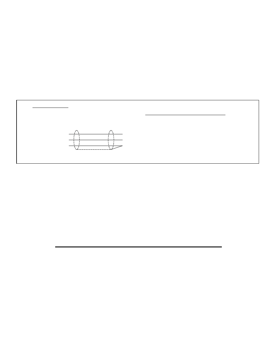
When hooking up to AW Flow Meters instrumentation, refer to the following drawing:
1. To prevent extraneous signal noise, ensure that a clean, central ground is established for both the flow
meter and sensor.
2. Where possible, keep the signal cable at least 1 foot from any cable handling 110 Volt AC. If several
signal cables are used, consider using metal conduit tubing for the signal cables for extra protection
and shield from external noise and EMI. If possible, ground the conduit at one end. Ground to a water
pipe or another good ground connection.
3. Place the pickup well away from motors, starters and relays. If used in a location where there are
starters and other controls using relays, be sure there are diodes mounted across the coils for DC
relays, and an R-C network for AC relays. This will dampen EMI from the relays when they operate.
4. Supply clean, regulated DC power with a ripple under 3% of supply
If the sensor appears faulty, review the following steps:
1. Detach the wiring connector from the sensor. Using a short wire, repeatedly touch pin A to C inside the
wiring connector. These simulated pulses should register at the instrument. If this does not occur, verify
that the wiring connections are set up as shown in Figure 2 above and check the instrument. If using a
non-AW instrument, check the specifications for signal compatibility.
2. If the pulses do register, re-attach the wiring connector to the sensor and rapidly move a screwdriver
back and forth 1/16” in front of the sensor nose. If pulses register, the sensor is okay. If not, contact the
factory for a return tracking number.
Note: If the sensor transmits a frequency irrespective of flow or by touch, the cable shielding and/or
grounding is faulty and the equipment is behaving as an antenna.
A
C
B
CAPM-2 or -3
PICKUP PINS
FEM-03
1
3
2
1 or 4
3 or 6
2 or 5
1
4
2
SHIELD
+ SUPPLY
SIGNAL
GROUND
INSTRUMENT CONNECTIONS
EMO-500
EMO-1005
JFC-01
4
5
3
CAPM-2o or -3o
CF-1 and HEF-1
EMO-3000
Figure 2