Van Air Systems High Dew Point Alarm Box User Manual
Page 4
PAGE 4
MAINTENANCE
SECTION 5
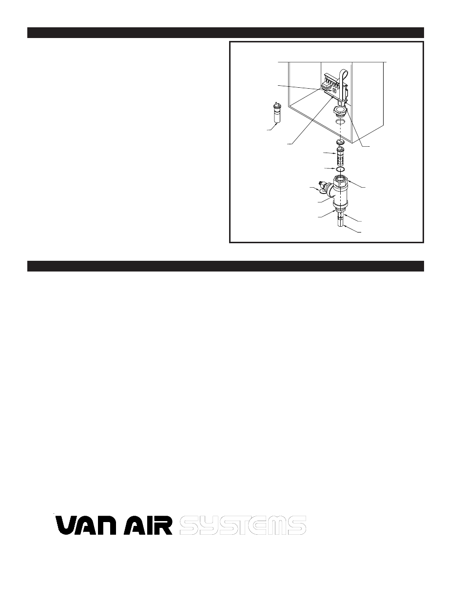
5.4 HUMISTAT CALIBRATION PROCEDURES
After the sampling line and power lines are connected, the humistat
must be adjusted as follows:
Unplug the cable from the dew point sensor.
Plug the set plug into the cable.
Apply power to the controller and adjust the potentiometer,
(REFERENCE FIGURE 5A), on the PC board. Rotate the
potentiometer back and forth, noting the position of the screw-
driver slot when the relay clicks as it pulls in and drops out. Set
the potentiometer midway between these two points.
Remove the set plug.
Plug the cable back to the dew point sensor.
The humistat is now ready for operation.
FIGURE 5A HUMISTAT DETAIL
REPLACEMENT PARTS
SECTION 6
ITEM NO
DESCRIPTION
PART NO
QTY
1
ISOLATION VALVE
14-1306
1
2
BLEED ORIFICE
26-0490
1
3
DEW POINT SENSOR
26-0817
1
4
SENSOR MOUNT
26-0816
1
5
CABLE
46-2185
1
6
HUMISTAT
26-0814
1
7
SET PLUG
26-0818
1
8
REPLACEMENT LIGHT BULB
26-0726
1
9
LIGHT ASSEMBLY (W/RED LENS)
26-2141
1
10
RESET PUSHBUTTON
26-3757
1
11
ORIFICE COUPLING
26-0657
1
12
ORIFICE BUSHING
26-0296
1
13
CONTROL RELAY
26-0813
1
14
MUFFLER
26-0623
1
2950 Mechanic Street
Lake City, PA 16423 USA
Phone: 800/840-9906
Corporate Fax: 814/774-0778
Order Entry Fax: 814/774-3482
www.vanairsystems.com
-5&&,%2
/2)&)#%
!.$
",%%$
3%.3/2
3!-0,%
)3/,!4)/.
/ 2).'
3%.3/2
#!",%
(5-)34!4
3%4
0/4%.4)/-%4%2