Van Air Systems AC 10-1 to 40-1 User Manual
Page 2
PAGE 2
© 1995 VAN AIR SYSTEMS INC. 2950 MECHANIC STREET, LAKE CITY, PA 16423
PRINTED IN THE U.S.A.
SPECIFICATIONS AND DIMENSIONS
SECTION 3
3.1 SPECIFICATIONS
WEIGHT
AC-10-1 ............... 25 LBS
AC-20-1 .............. 27 LBS
AC-30-1 ............... 61 LBS
AC-40-1 .............. 67 LBS
DIMENSIONS .............. See Section 3.2
INLET/OUTLET CONNECTIONS
AC-10-1 ........ 1/2" NPT (F)
AC-20-1 ...... 1/2" NPT (F)
AC-30-1 ........ 1" NPT (F)
AC-40-1 ..... 1-1/2" NPT (F)
MAXIMUM WORKING PRESSURE
ALL MODELS ............ 250 PSIG
MAXIMUM WORKING TEMPERATURE
ALL MODELS ............ 350
O
F
ASSEMBLY, LEG INSTALLATION
SECTION 2
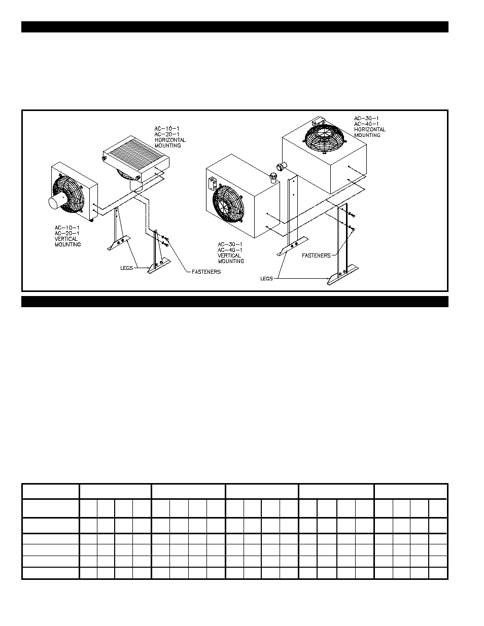
2.1 INSTALLING THE LEGS
This unit was shipped without the legs installed. The legs
should be installed before placing the aftercooler in the
piping system.
The legs can be mounted two ways:
1. Core mounted horizontally
2. Core mounted vertically
FIGURE 1 LEG INSTALLATION DETAIL
ELECTRICAL REQUIREMENTS
ALL MODELS ............ 115V-1PH-60Hz, w/ ODP motor
MATERIALS OF CONSTRUCTION
CABINET .................... Steel with baked enamel finish
FAN GUARD .............. Steel, zinc chromate plated
FAN ............................ Heavy gauge aluminum with steel hub
CORE ......................... Aluminum fins on copper tubes
MOTOR ...................... Open vented
MOTOR SPECIFICATIONS AND DATA
See Wiring Diagram, Figure 5 on page 6.
FAN DATA
(AMBIENT AIR FLOW)
AC-10-1 & AC-20-1 .... 615 SCFM
AC-30-1 & AC-40-1 .... 945 SCFM
MAXIMUM CAPACITY (SCFM)
Rated capacities are based on the following conditions: Inlet and approach temperature at inlet pressures 80 to 125 PSIG.
Approach Temperature: The number of degrees above the temperature of the cooling medium (in this case ambient air) to
which the aftercooler reduces the compressed air. A higher approach does not mean better performance.
INLET TEMP.
APPROACH
TEMP.
O
F
MODEL
AC-10-1
AC-20-1
AC-30-1
AC-40-1
15
35*
43*
72*
125*
10
35*
43*
72
125*
5
17
29
43
95
20
35*
43*
72*
125*
5
11
17
28
66
10
22
36
50
111
15
35
43*
70
125*
20
35*
43*
72*
125*
5
8
12
22
52
10
16
27
35
88
15
20
35
50
100
20
35
43*
70
125*
5
6
10
18
44
10
12
20
32
74
15
19
31
45
100
20
26
42*
57
125
5
5
8
15
38
10
10
16
28
64
15
15
26
39
86
20
21
35
50
108
150
O
F
200
O
F
350
O
F
250
O
F
300
O
F
MAXIMUM PRESSURE DROP LESS THAN 3 PSI.
*
Maximum ratings restricted by pressure drop: actual thermal capacities are higher.
Determine the desired position for your installation. Place the
aftercooler in that position (horizontal or vertical). Carefully lift
and support the unit approximately 1 to 2 feet from the floor.
Position the legs against the unit and fasten them in place
using the fasteners provided. Make sure the fasteners are
tightened in place.