Ft7000 – Triton FT7000XP Installation Manual User Manual
Page 41
41
FT7000
XP
- S
ITE
P
REPARATION
AND
I
NSTALLATION
G
UIDE
S
TEP
5:
(Outside facility) Remove the trim hardware brackets.
(Inside facility) Move the unit (you may have to raise the plinth assembly) to drill/install anchor
bolts. Move unit back through opening, lower plinth assembly to floor (if applicable), and anchor unit.
S
TEP
4:
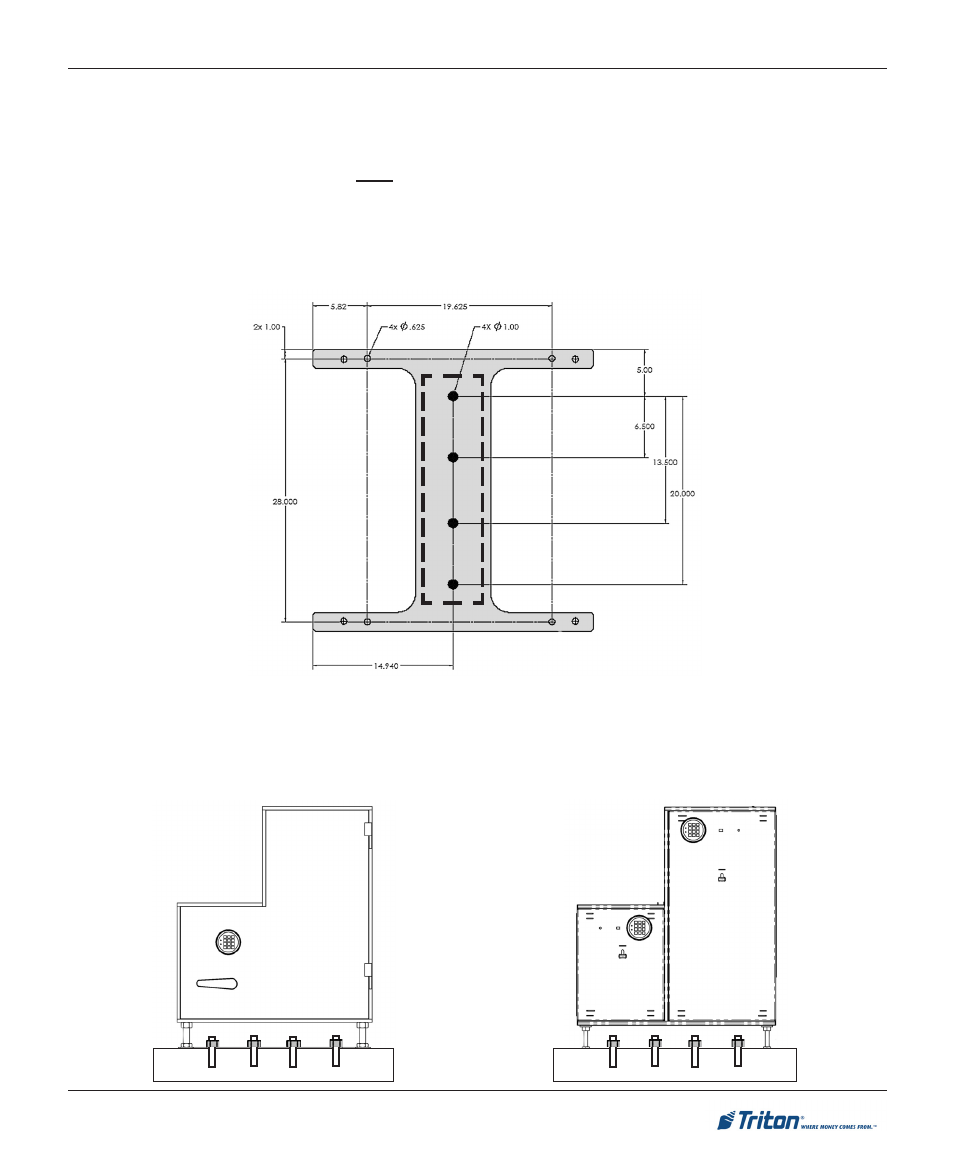
Inside facility - lower the leveling feet (plinth assembly) to the interior floor, if applicable. Mark the anchor
holes. See dotted lines below for anchor hole placement.
12345678901234567890123456789012123456
12345678901234567890123456789012123456
12345678901234567890123456789012123456
12345678901234567890123456789012123456
12345678901234567890123456789012123456
12345678901234567890123456789012123456
12
12
12
12
1
1
1
1
1
1
1
1
1
1
1
1
123456789012345678901234567890121234567
123456789012345678901234567890121234567
123456789012345678901234567890121234567
123456789012345678901234567890121234567
123456789012345678901234567890121234567
123456789012345678901234567890121234567
1
1
1
1
1
1
1
1
1
1
1
1
12
12
12
12
S
TEP
3:
Move unit so collar brackets are as close to flush against wall.
Note: If there are uneven gaps between brackets and wall (ex: larger gap on bottom), this may be
tightened by adjusting leveling feet after unit is anchored.