9100 c, Electronic lock installation procedure – Triton 9100 Electronic Lock Installation Manual User Manual
Page 4
T
RITON
S
YSTEMS
E
LECTRONIC
L
OCK
I
NSTALLATION
M
ODEL
9100 C
ASH
D
ISPENSER
4
Electronic Lock Installation Procedure
After removing the mechanical lock, follow these steps
to install the electronic combination lock:
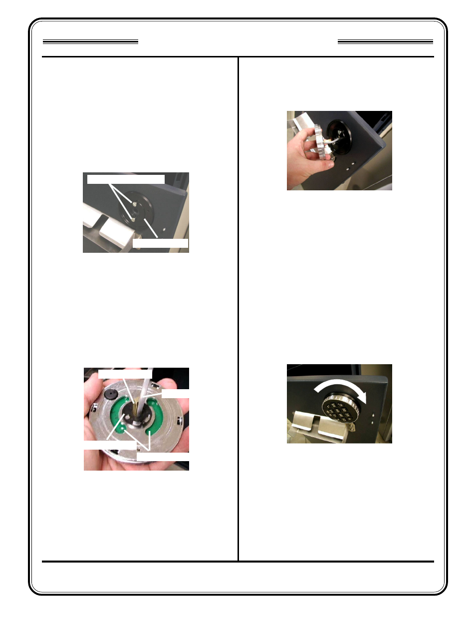
1.
Apply a small amount of Locktite to the threads of
the included #8-32 shoulder screws. Attach the
keypad mounting plate to the cabinet door using
the two shoulder screws.
2.
Place the 1-inch long brass spindle into the back
of the Electronic Lock Keypad as shown below.
Make sure the cable is positioned in the channel
on the brass spindle. Slide the keypad bushing
over the cable and the spindle so that it fits flat on
the back of the keypad.
3.
Insert the end of the keypad cable through the hole
in the mounting plate and align the shoulder screws
with the mounting slots in the back of the keypad.
4.
Align the large holes in the keypad mounting slots
with the heads of the shoulder screws. Place the
keypad on the shoulder screws and turn it about 10
degrees clockwise to lock it onto the mounting
plate. The keypad should turn freely.
IMPORTANT: If the keypad DOES NOT turn freeIy,
remove the keypad, back the shoulder screws
out 1/4-turn, replace the keypad and check the
fit again. Continue this process until the keypad
turns freely.
Figure 4. Turn 10 degrees clockwise to
lock to mounting plate.
Figure 2. Insert Brass Spindle. Slide
Keypad Bushing over spindle and cable.
The keypad mounting slots are used to
attach keypad to mounting plate.
Brass Spindle
Cable
Keypad Bushing
Mounting Slots
Figure 1. Attach Electronic Lock
Mounting Plate.
Figure 3. Insert keypad cable through
hole in mounting plate. Align large holes
in keypad mounting slots with shoulder
screws on mounting plate.
Mounting Plate
#8-32 Shoulder Screws