SANDPIPER ELECTRO-PNEUMATIC SPEED CONTROL SYSTEM User Manual
Page 3
spdctrol-rev0808
Speed Control Page 3
WARREN RUPP, INC. • A Unit of IDEX Corporation • P.O. Box 1568 • Mansfi eld, OH 44901 USA • (419) 524-8388 Fax (419) 522- 7867
www.warrenrupp.com
INSTALLATION & CONNECTION
Mechanical Connections: Plumb the outlet of
the air piloted regulator (procedure explained earlier) to
the inlet of the diaphragm pump. Plumb the inlet of the
air piloted regulator to the supply air. Supply air must
be clean, dry compressed air, not to exceed 125 psi.
Mount the control box in desired location.
Electrical Connections: The Warren Rupp
Speed Control System 032-022-000 is shipped
standard, set up for 110V. Speed Control System
032-023-000 is shipped standard, set up for 220V.
The units are marked accordingly on the exterior and
interior of the Power Supply Module. Be certain you
have the correct unit before installing. Connect
the AC incoming power to terminal on Power Supply
marked L1 and L2.
DO NOT USE neutral (ground) wire.
If the Warren Rupp Speed Control is to be used
as a stand-alone control device (no remote controller
used to provide command signal) the switch on the
outside of the control box ("Manual/Automatic") should
remain in the Manual position. In this scenario, any
desired changes in pressure output of the valve are
made by simply adjusting the potentiometer knob on
the face of the control panel. Clockwise turning of the
potentiometer increases the pressure speed and out-
put. Counter clockwise movement decreases speed
and output.
NOTE: Each input volt equals 12.5 psi output
pressure. For example, at 65 psi input, the potenti-
ometer would operate between minimum and half-
way to maximum on the dial to achieve maximum
performance of this unit. (See Fig. 6).
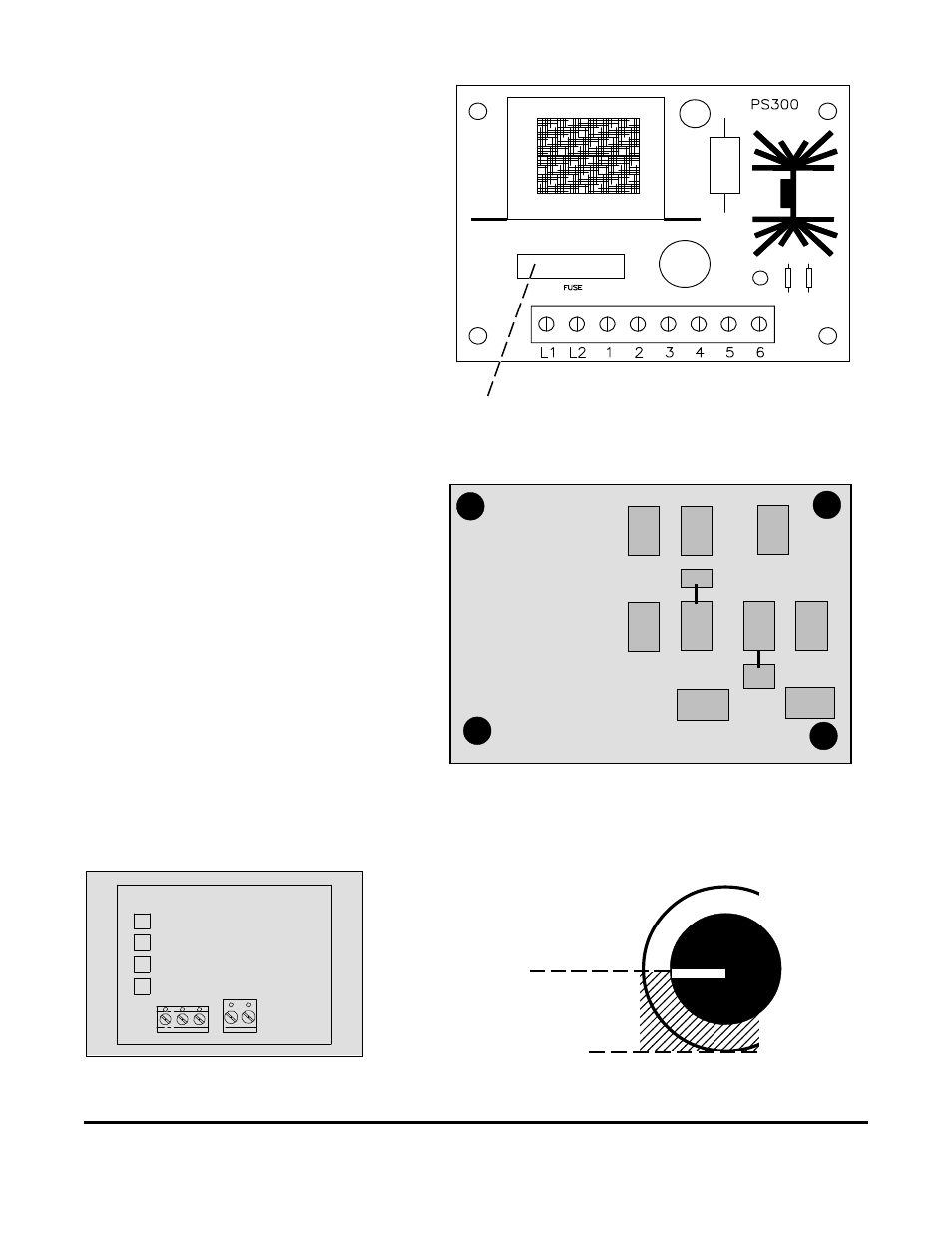
If a remote controller is used to provide a 4-20
mA command signal, locate the small circuit board on
the inside of the face plate of the control box. Connect
4-20 + to terminal marked S+. Connect 4-20 - to terminal
marked S-. (See Figure 5.) In this scenario, when the
switch on the outside of the control box marked Manual/
Automatic is in the Manual position, the command sig-
nal is from the potentiometer on the face of the control
panel. When the switch is in the Automatic position,
the command signal comes from the 4-20 mA control
signal supplied by the remote controller.
Front View of Power Supply Module
Figure 5
PS-300
A
B
C
D
E
F
Figure 4
Rear View of Power Supply Module
3 amp Fuse: Replacement Part 358-001-000
Minimum
Maximum
Operating range of this unit
at 65 psi input pressure.
This setting represents
maximum performance at
approximately 65 psi input
pressure.
Figure 6
Do not exceed 125 psi input
pressure.
POTENTIOMETER
MANUAL CONTROL KNOB
S-
S+