Explanation of pump nomenclature, M15 non-metallic · design level 3 · ball valve – SANDPIPER M15 Non-Metallic User Manual
Page 4
m15nmdl3sm-rev0713
Model M15 Non-Metallic Page 2
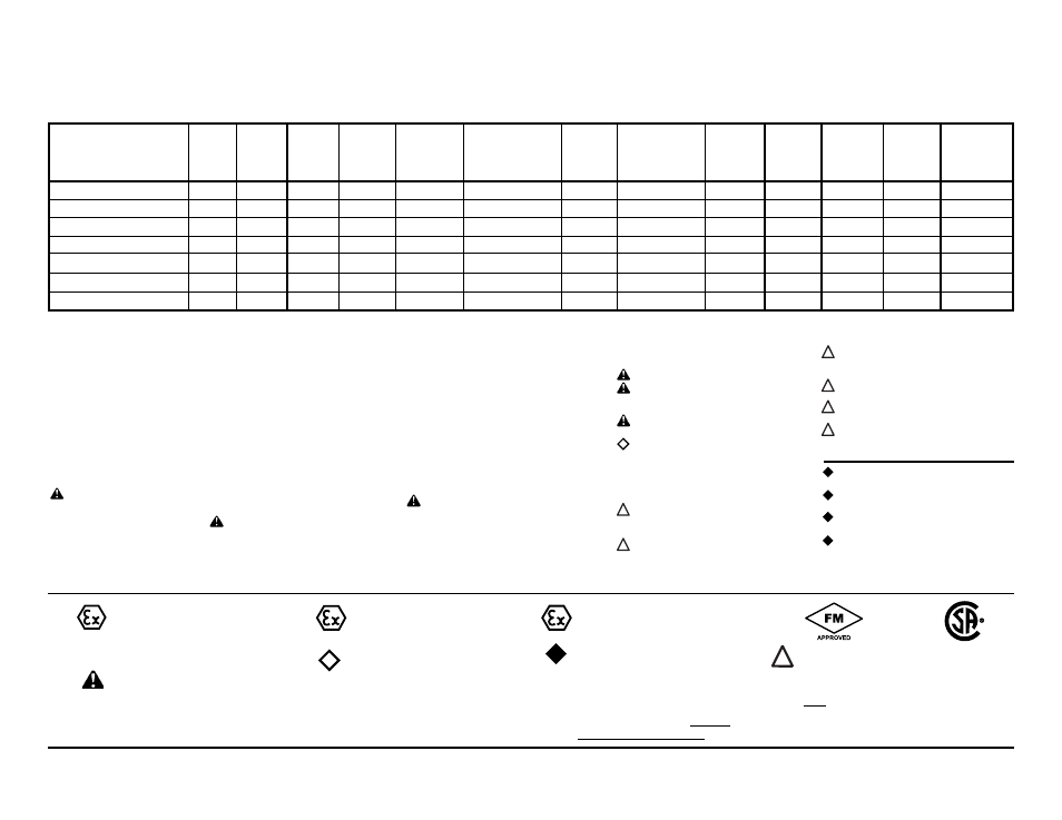
Check
Diaphragm/
Check
Non-Wetted
Shipping
Model
Pump Pump Valve Design Wetted
Check Valve Valve
Material
Porting Pump Pump
Kit
Weight
Brand Size
Type
Level Material
Materials
Seat
Options Options Style Options Options lbs. (kg)
M15B3P1PPAS000.
M
15
B 3 P
1
P P A S 0 00.
80 (36)
M15B3K1KPAS000.
M
15
B 3 K
1
K P A S 0 00.
108
(49)
M15B3P2PPAS000.
M
15
B 3 P
2
P P A S 0 00.
83
(34)
M15B3K2KPAS000.
M
15
B 3 K
2
K P A S 0 00.
112
(51)
M15B3PGPPAS000.
M
15
B
3
P
G
P
P
A
S
0
00
109 (50)
M15B3KGKPAS000.
M
15
B 3 K
G K P A S 0 00
112
(51)
M15B3C1PCAS000.
M
15
B 3 C
1
P C A S 0 00.
84(38)
M15 Non-Metallic · Design Level 3 · Ball Valve
Explanation of Pump Nomenclature
Pump Brand
M= MARATHON
®
Pump Size
15=1 1/2"
Check Valve Type
B= Ball
Design Level
3= Design Level 3
Wetted Material
K= PVDF
P= Polypropylene
C=Conductive Polypropylene
Diaphragm / Check Valve Materials
1= Santoprene/Santoprene
2= PTFE-Santoprene Backup/PTFE
6= PTFE Pumping, PTFE-Neoprene
Backup Driver/PTFE
B= Nitrile/Nitrile
C= FKM / PTFE
G=PTFE-Neoprene Backup/PTFE
N=Neoprene/Neoprene
U=Urethane/Urethane
Z= One-Piece Bonded/PTFE
Check Valve Seat
K= PVDF
P= Polypropylene
Non-Wetted Material Options
C=Carbon Filled Conductive
Polypropylene
P=40%Glass Filled Polypropylene
1=40%Glass Filled Polypropylene
w/PTFE Coated Hardware
Porting Options
A= ANSI Flange
D= DIN Flange
7= Dual Porting (ANSI)
8= Top Dual Porting (ANSI)
9= Bottom Dual Porting (ANSI)
Pump Style
D= with Electronic Leak Detection (110V)
E= with Electronic Leak Detection (220V)
M=with Mechanical Leak Detection
S= Standard
V= with Visual Leak Detection
Pump Options
0= None
1= Sound Dampening Muffler
2= Mesh Muffler
3= High temperature Air Valve
w/Integral Muffler
4= High temperature Air Valve
w/Sound Dampening Muffler
Kit Options
continued
E5.= Solenoid Kit with 110VAC
Explosion-Proof Coil
E6.= Solenoid Kit with 220VAC Coil
E7.= Solenoid Kit with 220VAC
Explosion-Proof Coil
E8.= Solenoid Kit with 110VAC, 50 Hz
Explosion-Proof Coil
E9.= Solenoid Kit with 230VAC, 50 Hz
Explosion-Proof Coil
SP.= Stroke Indicator Pins
A1.= Solenoid Kit with 12 VDC
ATEX Compliant Coil
A2.= Solenoid Kit with 24 VDC
ATEX Compliant Coil
A3.= Solenoid Kit with 110/120 VAC
50/60 Hz ATEX Compliant Coil
A4.= Solenoid Kit with 220/240 VAC
50/60 Hz ATEX Compliant Coil
Pump Options continued
5= High temperature Air Valve
w/Mesh Muffler
6= Metal Muffler
7= Metal Muffler w/ Grounding Cable
Kit Options
00.= None
P0.= 10-30VDC Pulse Output Kit
P1.= Intrinsically-Safe 5-30VDC,
110/120VAC 220/240 VAC
Pulse Output Kit
P2.= 110/120 or 220/240VAC
Pulse Output Kit
E0.= Solenoid Kit with 24VDC Coil
E1.= Solenoid Kit with 24VDC
Explosion-Proof Coil
E2.= Solenoid Kit with 24VAC/12VDC Coil
E3.= Solenoid Kit with 12VDC
Explosion-Proof Coil
E4.= Solenoid Kit with 110VAC Coil
Note: Models listed in the table are for reference only. See nomenclature below for other models.
*Note: See page 20 for
Special
Conditions For Safe Use.
Note: Pumps are only ATEX
compliant when ordered with
wetted material option C, non-
wetted material option C, pump
option 0, 6 or 7, and kit option 0.
II 2GD T5
(1)
Note: Pumps ordered
with the options listed in
(1) to the left are ATEX
compliant when ordered
with kit option P1.
II 2G Ex ia c IIC T5
II 2D c iaD 20 IP67 T100˚C
(2)
Note: Pumps ordered with the options listed
in (1) to the left are ATEX compliant when
ordered with kit option A1, A2, A3, or A4.
Compressed Air Temperature Range: Maxi-
mum Ambient Temperature to plus 50°C.
II 2G EEx m c T5
II 2D c IP65 T100°C
(3*)
IEC EEX m T4
Note: Pump models equipped with these
explosion-proof solenoid kit options E1,
E3, E5, E7, E8 or E9, are certified and
approved by the above agencies. They are
NOT ATEX compliant.
(4)
II 1G c T5
II 3/1 G c T5
II 1D c T100°C
I M1 c
I M2 c
II 2G Ex ia c IIC T5
II 3/2 G Ex ia c IIC T5
II 2D Ex c ia 20 IP67 T100°C
II 2G EEx m c II T5
II 3/2 2G EEx m c II T5
II 2D c IP65 T100°C