Solenoid shifted air valve drawing – SANDPIPER M05 Non-Metallic User Manual
Page 20
m05nmdl2sm-rev0114
Model M05 Non-Metallic Page 18
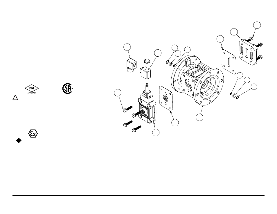
38
8
20
26
39
30
26
39
30
4
22
35
12
36
37
solenoID shIFTeD aIr ValVe ParTs lIsT
(Includes all items used on Composite Repair Parts List except as shown)
Item
Part number
Description
Qty
4
114-023-551
Bracket, Intermediate
1
35
893-099-000
Solenoid Valve, NEMA4
1
36
219-001-000
Solenoid Coil, 24VDC
1
219-004-000
Solenoid Coil, 24VAC/12VDC
1
219-002-000
Solenoid Coil, 120VAC
1
219-003-000
Solenoid Coil, 240VAC
1
37
241-001-000
Connector, conduit
1
241-003-000
Conduit Connector with
1
Suppression Diode (DC Only)
38
171-065-115
Capscrew, Flanged 1/4-20 x 1.00
4
39
618-050-150
Plug (Replaces Item 7)
2
solenoid shifted air Valve Drawing
IEC EEX m T4
For Explosion Proof Solenoid Coils used in North America and
outside the European Union.
36
219-009-001
Solenoid Coil, 120VAC 60 H
z
1
219-009-002
Solenoid Coil, 240VAC 60 H
z
1
219-009-003
Solenoid Coil, 12VDC
1
219-009-004
Solenoid Coil, 24VDC
1
219-009-005
Solenoid Coil, 110VAC 50 H
z
1
219-009-006
Solenoid Coil, 230VAC 50 H
z
1
Item 37 (Conduit Conductor) is not required
*special Conditions For safe Use
A fuse corresponding to its rated current (max. 3*I
rat
according IEC 60127-2-1) or a motor protecting switch with short-circuit and thermal instantaneous tripping (set to rated current) shall be connected in
series to each solenoid as short circuit protection. For very low rated currents of the solenoid the fuse of lowest current value according to the indicated IEC standard will be sufficient. The fuse may be
accommodated in the associated supply unit or shall be separately arranged. The rated voltage to the fuse shall be equal to or greater than the stated rated voltage of the magnet coil. The breakage
capacity of the fuse-link shall be as high as or higher than the maximum expected short circuit current at the location of the installation (usually 1500 A). A maximum permissible ripple of 20% is valid for
all magnets of direct-current design.
II 2G EEx m c T5
II 2D c IP65 T100°C
For ATEX Compliant Solenoid Coils used in the European Union
36
219-011-001 Solenoid Coil, Single mounting 12 VDC, 3.3W / 267mA
1
219-011-002 Solenoid Coil, Single mounting 24 VDC, 3.3W / 136mA
1
219-011-003 Solenoid Coil, Single mounting 110/120 VAC, 3.4W / 29mA
1
219-011-004 Solenoid Coil, Single mounting 220/240 VAC, 3.4W / 15mA
1
Note: Item 37 (Conduit Connector) is not required
*
II 2G EE
x
m
c
II T5
II 3/2 G E
x
m
c
II T5
II 2D
c
IP65 T100°c
Compressed air Temperature range: Maximum Ambient Temperature to plus 50°C