Air valve with stroke indicator assembly, Atex compliant, Air distribution valve servicing – SANDPIPER S05 Metallic User Manual
Page 17
s05mdl1sm-rev0614
sandpiperpump
.
com
Model S05 Metallic •
14
1-E
1-F
1-C
1-D
1-B
1-B
1-A
1-G
1-E
1-F
1-C
1-D
1-J
1-K
1-H
1-I
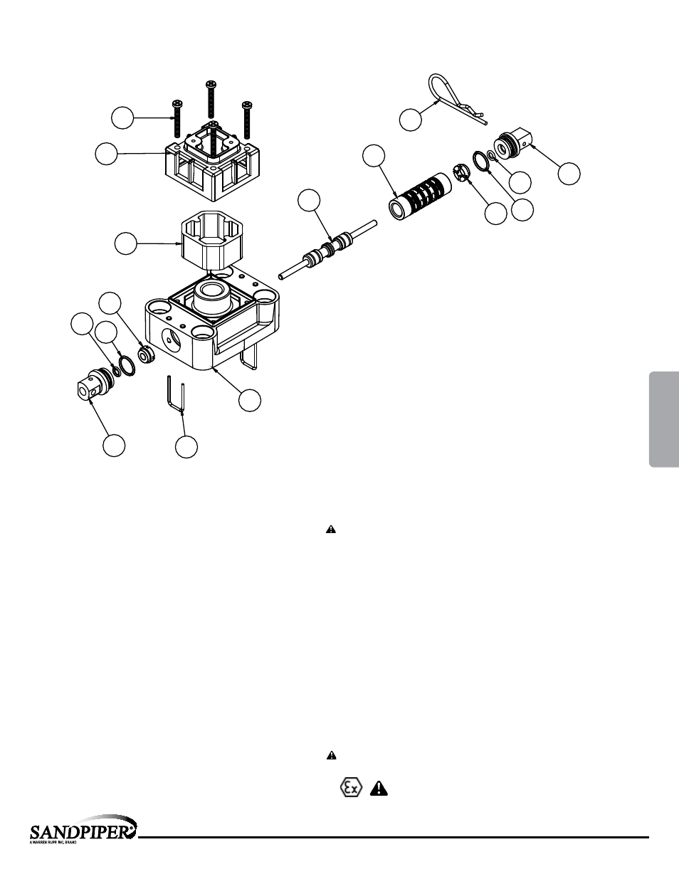
Main Air Valve Assembly Parts List
Item
Part Number
Description
Qty
1
031.167.000
Air Valve Assembly
1
1-A
095.106.559
Body, Air Valve
1
1-B
031.134.000
Sleeve and Spool Set
1
1-C 560.101.360 O-Ring
8
1-D 132.030.552 Bumper
2
1-E
165.123.147
End Cap
2
1-F 560.029.360 O-Ring
2
1-G
675.062.115
End Cap Retainer
2
1-H
210.008.330
Safety Clip
1
1-I
530.031.550
Muffler
1
1-J
165.109.559
Muffler Cap
1
1-K
710.011.115
Self-Tapping Screw
4
For Pumps with Virgin PTFE coated hardware:
1
031.167.002
Air Valve Assembly
1
1-G
675.062.308
End Cap Retainer
2
1-J
710.011.308
Self Tapping Screw
4
(Includes all other items used on 031.166.000 above)
For Pumps with alternate Mesh Muffler or Piped Exhaust:
1
031.169.000
Air Valve Assembly
1
(Includes all items used on 031.167.000 above minus 1-H, 1-I and 1-J)
ATEX Compliant
1-l
Air Valve with Stroke Indicator Assembly
Air Distribution Valve Servicing
See repair parts drawing, remove screws.
Step 1: Remove end cap retainer (1-G).
Step 2: Remove end cap (1-E), bumper (1-D).
Step 3: Remove spool part of (1-B) (caution, do not scratch).
Step 4: Press sleeve (1-B) from body (1-A).
Step 5: Inspect O-Rings (1-C) and replace if necessary.
Step 6: Lightly lubricate O-Rings (1-C) on sleeve (1-B).
Step 7: Press sleeve (1-B) into body (1-A).
Step 8: Reassemble in reverse order.
Note: Sleeve and spool (1-B) set is match ground to a specified clearance
sleeve and spools (1-B) cannot be interchanged.
4: AIR
END