Chamber porting, Air supply, Operation – SANDPIPER ST40 User Manual
Page 9: Freezing or icing of exhaust, Air exhaust, Maintenance after use
st15dl4sm-rev0614
Models ST1½, ST40 Page 7
ST1½-A volume for non-overlay = 1200ml / 40.6 fl. oz.
Use pipe dope on pipe plugs. Cast iron fluid chambers typically filled with normal
antifreeze.
CHAMBER PORTING
This unit is equipped with ball check valves and is furnished with side chamber porting
as standard. This arrangement is suitable for most pumping applications. A conversion
kit of elbows is available for optional top or bottom porting when required. Top porting is
recommended for operation at extremely low flow rates and high discharge pressures,
to eliminate accumulated air or vapor from the pumping chamber.
AIR SUPPLY
DO NOT CONNECT unit to air supply in excess of 125 PSI (8.61 Bars). Install a shutoff
valve in the air supply line to permit removal of the unit for servicing. When connecting the
unit to an air supply of rigid piping, use a section of flexible line to the pump to eliminate
piping strain.
OPERATION
This pump has been tested prior to shipment and is ready for use as received.
Make certain that the capacity at which the pump is operating is not limited by
the suction conditions involved (see installation procedures). Keep in mind that the
diaphragms will move at a rate proportional to inlet air flow. If the cycling rate is allowed
to exceed the rate that liquid can enter the chamber that is on the suction stroke the liquid
is simply pulled apart (cavitation) and the pump’s displacement is reduced. For the most
efficient use of compressed air and longest diaphragm service life, always throttle the air
inlet to the lowest cycling rate that does not decrease the flow rate.
Start the unit by opening the air inlet valve approximately ½ to ¾ turn. After the unit
starts pumping the air inlet valve can be opened to increase the pumping capacity as
desired. When further opening of the valve increases the cycling rate without an increase
in capacity, cavitation exists; and the valve should be closed slightly.
FREEZING OR ICING OF EXHAUST
Icing of air exhaust can occur under certain conditions of temperature and humidity
on all compressed air powered equipment. When performance loss due to icing is
experienced, use of an air dryer should eliminate this condition. Icing will be more
prevalent at high discharge pressures.
AIR EXHAUST
SANDPlPER pumps can be submerged if the materials of construction are compatible
with the liquid and the exhaust is piped above the liquid level. Piping used for the exhaust
should not be smaller than 1" (2.54 cm) pipe size. Reduced pipe size can restrict the
exhausted air and cause reduced pump performance.
When the product being pumped is at a level above the pump (flooded suction), the
exhaust should be piped to a higher level than the product in order to prevent spillage
caused by siphoning.
MAINTENANCE AFTER USE
When this pump is used to handle materials that settle out or transform from a liquid
to a solid form, care must be taken after each use and during idle periods to remove or
flush these materials from the pump as required. Failure to do this could result in possible
premature diaphragm failure.
To drain liquid from the pump, turn the unit over on the manifold side. This position
puts the chamber ports down and will allow the check balls to fall away from the seats
allowing complete draining of the unit. This procedure is important to ensure complete
draining in freezing weather.
NOTE: See note concerning operation of unit in freezing
conditions in “Installation Procedures”.
On permanent installations the pump chambers can be drained by removing the drain
plug in each outer chamber.
MAINTENANCE NOTE
A preventative maintenance procedure should be established to check the PTFE
pumping diaphragms for wear. Even though this part was proven to be good for millions
of cycles, the service life will vary with each application depending on the abrasive nature
of the liquid being pumped.
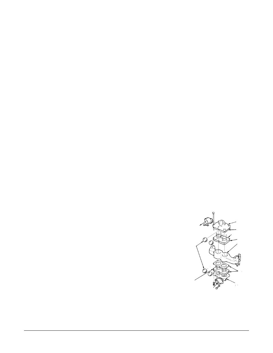
OUT
Fig. 1 Check Valve Servicing
Ball
Valve
Seat
Ball
Check
Valve
Discharge
Flange
Gasket
Gasket
Gasket
Suction
Flange
Ball Valve Seat
Suction/
Discharge
Manifold