Check valve servicing, Diaphragm servicing – SANDPIPER ST40 User Manual
Page 10
st15dl4sm-rev0614
Models ST1½, ST40 Page 8
The choice of the PTFE unit indicates that the material being handled is not compatible
with the standard materials of construction (Neoprene and aluminum). If a pumping
diaphragm (PTFE) were to fail, the unit would continue pumping via the driver diaphragm.
The elastomeric driver diaphragm would then be exposed to the liquid and failure of this
diaphragm due to attack would be the end result. At this point additional damage can
occur to the air valving portion of the pump and other internal parts and castings.
CHECK VALVE SERVICING
For best priming and most efficient pumping performance, it is important to maintain
check valves and valve seats in good condition for proper sealing. Need for inspection
or service of ball valves is usually indicated by poor priming, unstable cycling, reduced
performance, or pump cycles but will not pump.
Inspection and service of check valves requires the removal of six bolts which provides
access to all four ball valves and both, suction and discharge, valve seats. New ball
check valves are 2¼" (5.715 cm) diameter and will require replacement when worn to
approximately 2" (5.08 cm) diameter.
DIAPHRAGM SERVICING
DRIVER DIAPHRAGMS
Drain the driver liquid from the driver chamber on the side to be serviced. This is
accomplished by removing the drain plug in the bottom of the driver chamber. Remove the
four (4) flange nuts that secure the manifold assembly to the pump chambers. Remove
the manifold assembly from the pump. Remove the eight (8) hex nuts that secure the
inner pumping diaphragm chamber assembly to the driver inner diaphragm chamber and
remove the assembly by pulling axially off the studs. This will permit a quick inspection of
the PTFE pumping diaphragm as well as the driver diaphragm. It is not required that the
pumping diaphragm chambers be separated to get to the driver diaphragms.
To remove the driver diaphragm, loosen the diaphragm assembly by turning it out of
the shaft using a
3
/
8
" (.9525 cm) Allen wrench. Once the assembly has turned, it can be
turned out by hand by use of the diaphragm. Removal of the opposite pumping chamber
assembly will allow removal of the second driver diaphragm assembly and the shaft as
a unit. The interior components consisting of the shaft seals and sleeve bearing are now
accessible for inspection or service as required.
To disassemble the driver diaphragm assemblies, clamp the inner diaphragm plate
around the outer diameter in a vise to hold it while you turn the center screw loose from
the back plate and the assembly will come apart.
To remove the shaft from a diaphragm assembly, hold the shaft in a clamping device
making sure to protect the shaft surface so as not to scratch or mar it in any way. Then
the diaphragm assembly will turn loose using an Allen wrench
3
/
8
" (.9525 cm) on the
center screw.
All procedures for reassembling the diaphragms are just in reverse of previous
instructions for disassembly. The diaphragms are to be installed with their natural bulge
outward or toward the outer diaphragm plate. Make sure that the inner diaphragm plate
is installed with the flat face against the diaphragm.
After all the components are in position in a vise and hand tightened, tighten with a
wrench to approximately 45 Ft./Lbs. (61.01 Newton meters) torque reading. After each
driver diaphragm assembly has been made thread one assembly into the shaft. Install this
subassembly into the pump and secure it by placing the pumping chamber assembly over
it and secure it in place with the eight (8) hex nuts. This will hold the diaphragm assembly
in place while the opposite side is installed. Make sure the last diaphragm assembly is
torqued into the shaft at 30 Ft./Lbs. (40.67 Newton meters). This final torquing will lock
the diaphragm assemblies together. Place the remaining pumping chamber assembly on
the open end and secure it by tightening the nuts gradually and evenly.
PUMPING DIAPHRAGMS
It is recommended that the above procedure be followed to the point of removing the
pumping chamber assembly from the unit. Remove the hex nuts and capscrews that
secure the assembly together and lift off the outer chamber from the assembly. This
exposes the PTFE pumping diaphragm and allows access to the o-ring seal behind it.
The re-assembly is just in reverse of the above as follows: Install the o-ring seal in the
groove provided on the inner chamber. Replace the PTFE diaphragm and place the outer
chamber on the assembly making sure that the chambers inlet-outlet port centerline is
perpendicular to the centerline formed by the fill and drain plugs in the inner chamber.
Replace all fasteners that secure the assembly together and torque them at 33 Ft./Lbs.
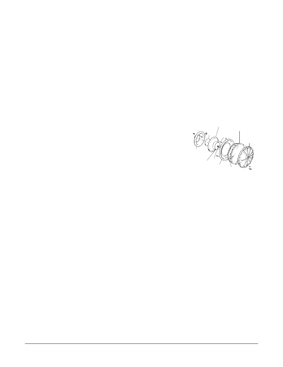
Flat Head
Capscrew
Outer
Diaphragm
Chamber
Inner
Diaphragm
Chamber
Diaphragm
Inner
Plate
Inner
Diaphragm
Chamber
“O” Ring
Outer
Diaphragm
Plate
Driver
Diaphragm
“O” Ring
PTFE®
Pumping
Diaphragm
Fig. 2 Diaphragm Servicing