Assembly – RIKON Power Tools 50-142 User Manual
Page 8
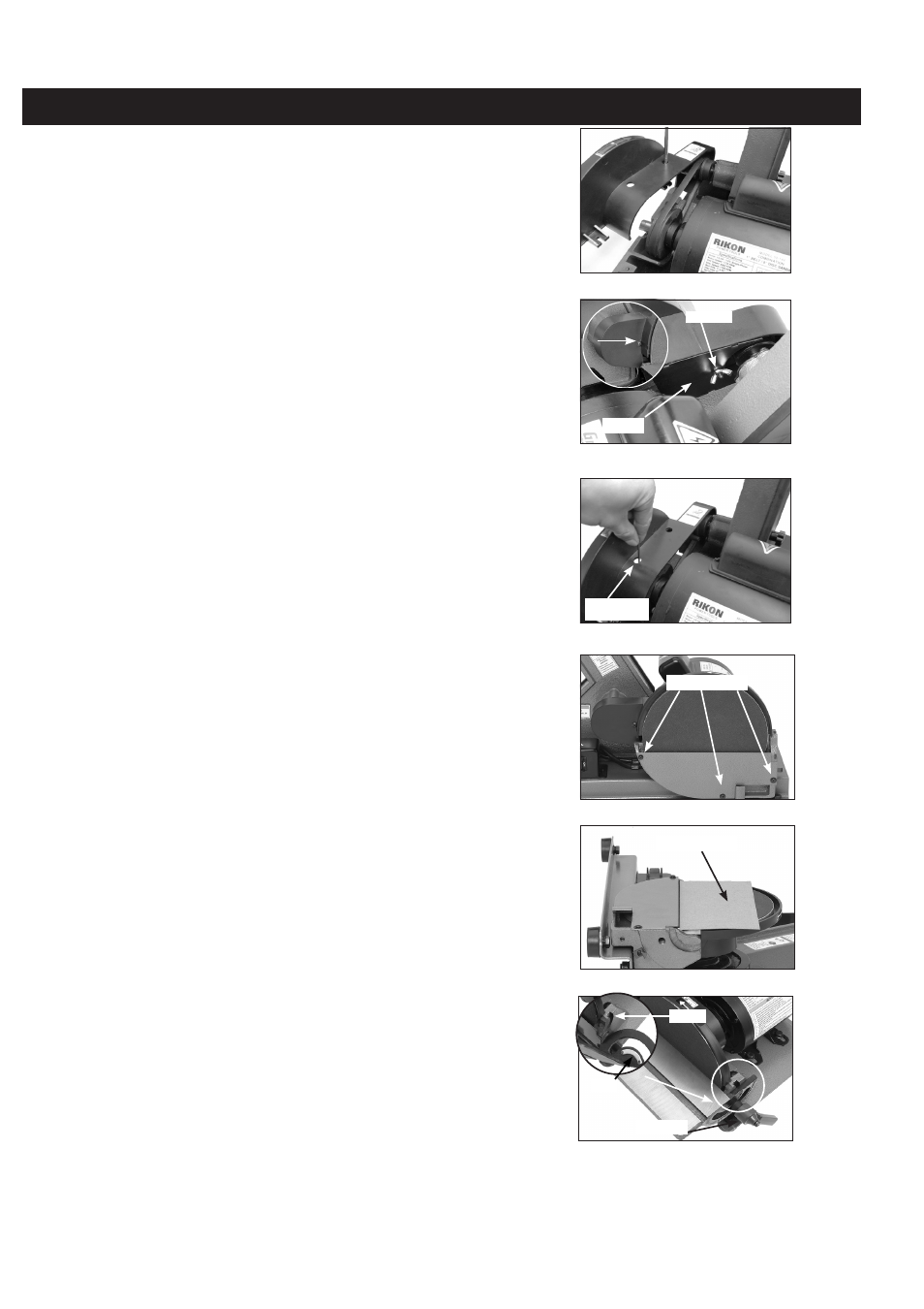
Fig.15
8
Assembly
Fig.11
Fig.12
10. Rotate the disc until you can see the set
screw through the hole on the back of the V-belt
safety cover (see Figure 13)
11. Using the 2.5mm hex wrench, tighten the set
screw to secure the disc to the motor arbor.
12. Install the disc dust cover, as shown in
Figure 14, with three M4-.7 x 10 Phillips head
screws and flat washers.
13. Lay the sander down on a flat surface, as
shown in Figure 15, and place a thin piece of
cardboard approximately 1⁄16” thick over the
sanding disc. This piece of carboard will act as a
spacer when you install the disc table.
14. Keeping the cardboard in place, align the
half-arc key of the disc table with the indented
keyway on the disc guard (see the inset of Fig-
ure 16). Then secure the table with a table lock
handle, and remove the cardboard.
15. Secure the dust port, as shown in Figure
17, with the M6-1 x 15 Phillips head screw and
flatwasher.
16. Square the disc table to the sanding disc
(refer to Squaring Disc Table on Page 14).
17. Using the M4-.7 x 10 Phillips head screw,
align the red scale pointer with the “0” mark on
the table angle scale (see Figure 18).
18. Install the belt table with a 1⁄16” clearance
from the sanding belt, and secure it in place with
the table lock handle (see Figure 19).
19. Loosen the cap screw shown in Figure 20,
adjust the belt support approximately 1⁄16” away
from the sanding belt, then re-tighten the cap
screw.
Set Screw
Access Hole
Fig.13
V-Belt
Fig.14
Keyway
Key
Fig.16
Table Lock
Mounting Screws
Wing Nut
Cardboard