RIKON Power Tools 10-201 User Manual
Page 8
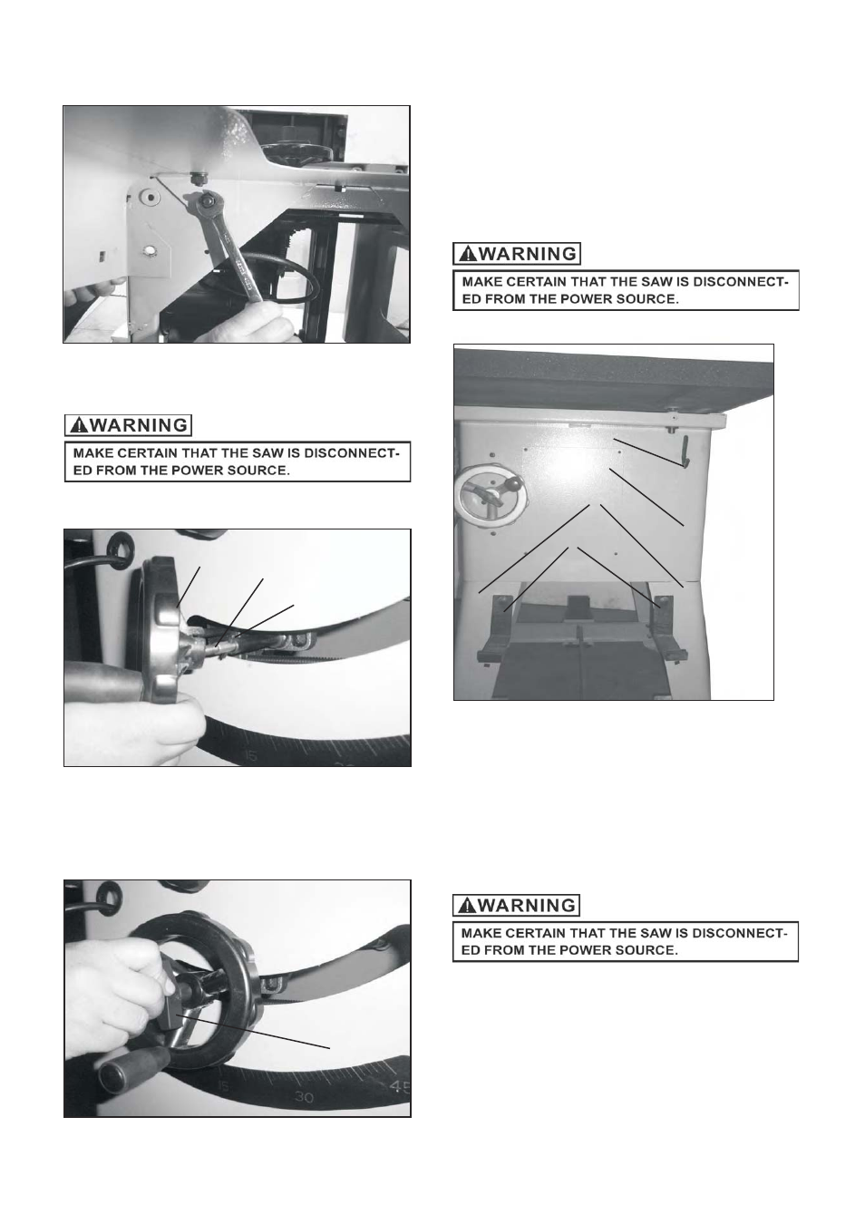
Fig.3
HANDWHEEL ASSEMBLY
Fig.4
A
B
C
1. Place one of the handwheels (A) onto the blade
raise/lower shaft (B) located on the front of the
cabinet. Align the groove in the back of the
handwheel with the pin (C). SEE FIG 4.
Fig.5
D
2. Thread the locking knob (D) onto the threaded end of
the shaft.
3. Repeat the steps above to assemble the remaining
handwheel and locking knob onto the bevel shaft
located on the side of the cabinet.
SEE FIG 5.
WRENCH AND FENCE HOOK
ASSEMBLY
8
Fig.6
1. Assemble both of the fence hooks (C) to the left
2. Assemble wrench hook (A) to the right side of cabinet
(D) using two M4X8mm round head tap screws.
and
right cabinet leg (B) using four M8x16mm
carriage screws, M8 flat washer, M8 lock washer and
M8 hex nut to tighten them.
SEE FIG 6
POLY-V BELT REPLACEMENT
1.
6
5 10
cross
A
Loosen
of M x
mm
pan head tap screws ( )
and remove the cabinet access door. SEE FIG. 7.
A
B
C
D
- 10-305 (24 pages)
- 10-308 (20 pages)
- 10-315 (28 pages)
- 10-321 (52 pages)
- 10-325 (28 pages)
- 10-346 (38 pages)
- 10-350 (32 pages)
- 10-370 (34 pages)
- 10-600VS (17 pages)
- 23-400 (22 pages)
- 23-400H (28 pages)
- 25-010 (26 pages)
- 25-010H (32 pages)
- 25-200 (26 pages)
- 25-200H (36 pages)
- 30-100 (24 pages)
- 30-120 (20 pages)
- 30-140 (21 pages)
- 30-240 (22 pages)
- 30-251 (21 pages)
- 34-250 (18 pages)
- 50-112 (18 pages)
- 50-120 (18 pages)
- 50-142 (24 pages)
- 50-150 (18 pages)
- 51-200 (14 pages)
- 60-100 (16 pages)
- 60-200 (16 pages)
- 61-200 (16 pages)
- 61-1250 (18 pages)
- 61-1600 (18 pages)
- 61-2400 (18 pages)
- 62-100 (16 pages)
- 63-100 (16 pages)
- 70-050 (16 pages)
- 70-100 (18 pages)
- 70-300 (28 pages)
- 70-425 (18 pages)
- 70-500 (28 pages)
- 80-805 (22 pages)
- 10-110 (27 pages)
- 10-300 (17 pages)
- 10-320 (22 pages)
- 10-340 (22 pages)