RIKON Power Tools 10-201 User Manual
Page 18
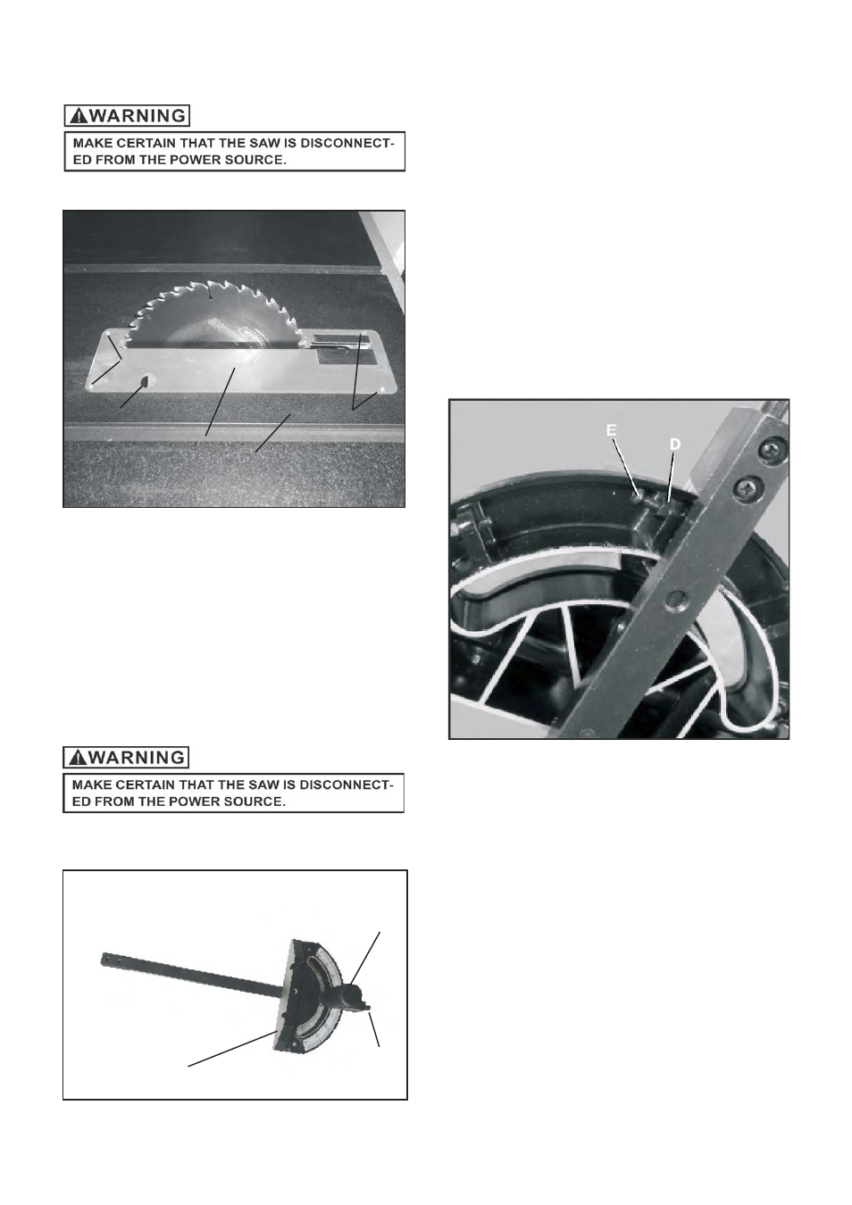
TABLE INSERT ADJUSTMENT
Fig. 40
1. The table insert (A) must always be level with the saw
table (B).
2. Place a straight edge across the front and rear of the
table insert. Check that the insert is perfectly level with
the saw table.
3. To level the table insert, turn the one or more adjusting
set screws (C) as needed and recheck.
5. The table insert is equipped with a finger hole (D) for
easy removal. SEE FIG. 40
1. The miter gauge has adjustable positive stops at 0-
degree and 45-degrees or it can be manually set at
any angle between 60-degrees.
2. To rotate miter gauge body (A), loosen knob (B) and
pull out plunger (C) and rotate miter gauge body to
desired angle and tighten knob.
3. To rotate to the next positive stop, pull plunger (C) out,
rotate miter gauge body then push plunger back in and
continue rotating miter gauge body until it stops
Against next positive stop.
SEE FIG. 41
A
B
C
D
C
MITER GAUGE ADJUSTMENT
ADJUSTING POSITIVE STOPS
Fig. 42
E
D
1. To adjust 0-degree positive stops, loosen knob (B), pull
out on plunger (C) and turn miter gauge over.
2. Loosen the lock nut (D) 3 or 4 turns.
3. Place a square against the guide bar and front of the
miter gauge body. Square the miter gauge body to the
guide bar and tighten knob.
4. Push in plunger and make adjustments to stop screw
(E) so that it touches the plunger and tighten lock nut.
5. Recheck the positive stop angle to the saw blade.
insert the guide bar into the miter slot and slide the
miter gauge up to the saw blade.
6. To check, place a square against the saw blade and
miter gauge body. If any more adjustments are needed
repeat steps above.
7. To set both 45-degree positive stops, repeat steps 1
Thru 6 above at the 45-degree settings.
SEE FIG 42.
18
Fig. 41
A
B
C