Frame assembly – Rhino Shelter ROUND-14W X 24L X 10H User Manual
Page 3
Assembly Instructions Boat/SUV Storage 14x24x10
planned so that it does not run into the unit. As well, rain
or melting snow that comes off the unit should be
drained away rather than accumulate and pool around
the unit.
Check to be certain that adequate clearance is allowed
for entry and exit from ends of unit. As unit has doors on
both ends, ideally boat or equipment can be inserted or
removed from either end.
Assembly Instructions V2.2
Please Do NOT Return Assembly to Dealer or Store. For All Assembly Questions or Shortages Please Call MDM Products Directly
Customer Service 800-447-7079 or 203-877-7070
3
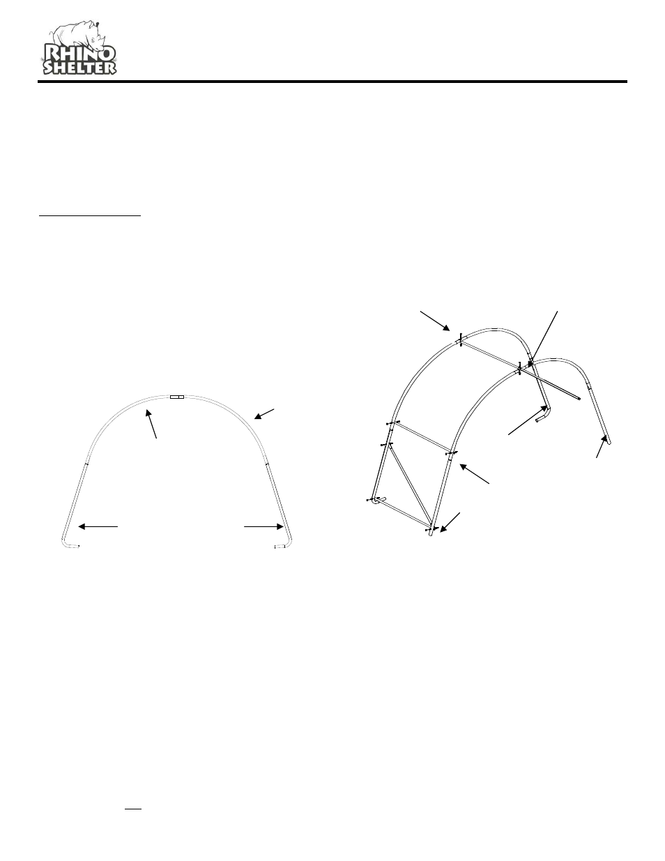
FRAME ASSEMBLY
Step1. Assemble the Front and Rear End Arch
Assemblies using (1) Right Side Crest Tube #RC-5020,
(1) Left Side Crest Tube #LC-5021 and (2) End Upright
w/Foot #EUL-5021 for each one. Use (4) #CBN-3005-2
carriage bolts with nuts and washers through pre-drilled
holes in frame members.
Be certain to insert carriage bolts from the outer edge
into the interior of the unit, with the washers and nuts on
the inside of the arches. This will avoid tearing the fabric
on doors and main cover when installed. Do not tighten
the nuts completely until the frame is completed and set
in place.
Step 2. Assemble the (2) Corner Wind Braces #CW-
2800 to the End Upright w/Foot #EUL-5021 to the first of
the End Arch assemblies. Use a #CBN-3005-3 Carriage
Bolt with Washer and Nut to secure the braces loosely to
the Upright. Do not tighten completely.
Step 3. Assemble the remaining four interior arches
using (1) Right Crest Tube #RC-5020, (1) Left Crest
Tube #LC-5021, and (2) Center Straight Upright #CSU-
5020 for each. Use CBN-3000-2 carriage bolts with
washers and nuts in the pre-drilled holes, aligned to form
the arch.
Step 4. Support an End Arch with Wind Braces #CW-
2800 temporarily in the vertical position. Connect (4)
ECR-5031 Plain End Cross Rails to the End Arch with
(4) CBN-3000-5 carriage bolts, washers, and nuts
through the pre-drilled holes in the arch members. The
Cross Rails should be put into the bottom and side hole
of the arch upright. Again, don’t tighten the hardware
until the next arch and cross rails are assembled. It is
very important to make certain all nuts are on the inside
of the unit to avoid damaging the cover when put on.
Stand an interior arch assembly up vertically into
position, so the cross rails align with the holes in the
interior arch. Using (4) Carriage Bolts #CBN-3000-3
with nuts and washers, connect the cross rails between
the end arch and the first interior arch assemblies.
Connect the (2) Wind Braces #CW-2800 diagonally
across the end and interior arch as shown in the frame
illustration.
As each interior arch is added, add a #SCR-5020
Swedged End Cross Rails to each base and side ridge
pole to make up rail assembly with each arch. Slip
swedged end of cross rail into plain end of prior cross
rail. It will be necessary to remove bolt to add cross rails
with each arch assembly.
Top Ridge
Under End
Arches
End Arch
Assembly
Side Ridge &
Base Ridge Poles
Inside unit
Interior
Arch
Assembly
Top Ridge Rail Over
Interior Arches
RC-5020 Right
Crest Tube
LC-5021 Left
Side Crest Tube
EUL-5021 End Upright
With Foot