Installation – Lincoln Electric IM764 RED-D-ARC EX350i User Manual
Page 10
A-3
INSTALLATION
A-3
LN-7 Connection Instructions
• Turn the EX350i power switch “off”.
• Connect the K480 control cable from the LN-7 to
the EX350i 115 VAC control cable connector.The
control cable connector is located at the front of the
EX350i.
• Connect the electrode cable to the output terminal
of polarity required by electrode. Connect the work
lead to the other terminal
• Set the meter polarity switch on the front of the
EX350i to coincide with wire feeder polarity used.
The wire feeder will now display the welding volt-
age.
• If K480 is not available, see connection diagram
S19404 for modification of K291 or K404 LN-7 input
cable with K867 universal adapter plug.
LN-10 Connection Instructions
• Turn the EX350i power switch "off"
• Connect the K1505 control cable from the LN-10 to the
EX350i 24/42VAC 14-pin amphenol connector on the
front of the EX350i.
• Connect the electrode cable to the output terminal of
polarity required by the electrode. Connect the work lead
to the other terminal.
• Set the meter polarity switch on the front of the EX350i to
coincide with wire feeder polarity used.
• See the LN-10 manual for details on accessing Control
DIP Switch
LN-742 Connection Instructions
• Turn the EX350i power switch "off"
• Either a K591 or a K593 Input cable assembly is
required to connect the LN-742 to the EX350i.
• Connect the control cable from the LN-742 to the
24/42 VAC 14-pin wire feeder amphenol on the
front of the EX350i.
• Connect the electrode cable to the output terminal
of the polarity required by electrode. Connect the
work lead to the other terminal.
• Set the meter polarity switch on the front of the
EX350i to coincide with wire feeder polarity used.
The wire feeder will now display the welding volt-
age.
• If a remote control is to be used with the LN-742,
use a K864 adapter to connect the feeder and a
K857 remote to the 14-pin wire feeder connector on
the front of the EX350i.
Cobramatic Connection Instructions
• Turn the EX350i power switch "off"
• Connect the control cable from the Cobramatic to
the 24/42 VAC 14-pin wire feeder amphenol on the
front of the EX350i.
• Connect the electrode cable to the output terminal
of the polarity required by electrode. Connect the
work lead to the other terminal.
• Set the meter polarity switch on the front of the
EX350i to coincide with wire feeder polarity used.
• If a remote control is to be used with the
Cobramatic, or use a K864 adapter to connect the
cobramatic and a K857 remote to the 24/42VAC
14-pin wire feeder amphenol connector on the front
of the EX350i.
TIG Module K930-2
The TIG Module connects to the EX350i with a K936-
1 (9-14 pin) control cable. Connect the K936-1 to the
115VAC wire feeder amphenol on the front of the
EX350i.
General Instructions for Connection of Wire
Feeders to EX350i
Wire feeders other than LN-7 and LN-25 may be used
provided that the auxiliary power supply capacity of
the EX350i is not exceeded. K867 universal adapter
plug is required. See connection diagram S24985 on
page F-4.
REMOTE CONTROL OF INVERTEC
Remote Control K857, Hand Amptrol K963 and Foot
Amptrol K870.
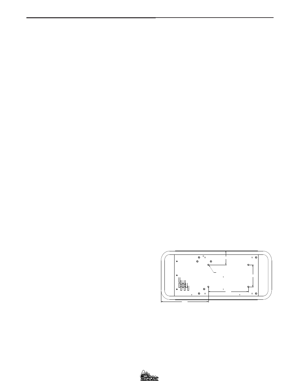
UNDERCARRIAGE MOUNTINGS
5.50
10.00
MOUNTING HOLE LOCATIONS
1/4-20 NUT (4 PLACES)
NOTE: MOUNTING SCREWS CANNOT PROTRUDE MORE THAN 0.5 INCHES INSIDE THE MACHINE.
3.50
11.84
EX350i