Calibration, External triggering circuit – Lincoln Electric IM573 POWER WAVE CALIBRATION PROCEDURES User Manual
Page 28
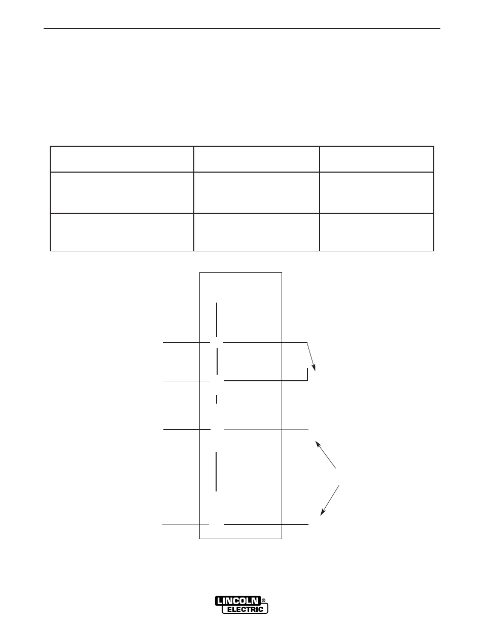
The Power Wave 450 Robotic may be triggered inde-
pendent of the robot using the following circuit and pro-
cedure.
1. Remove the large connector plug on the rear of the
PW450. (As viewed from the front of the machine).
2. Connect a normally open switch and a 24VDC sup-
ply either to the large connector plug (P82) or to the
harness connectors on the interface board. See the
following table and figure.
3. When the 24VDC supply is correctly wired in place
and turned on the welding output terminals can be
energized by closing the switch.
CALIBRATION
28
28
POWER WAVE CALIBRATION
EXTERNAL TRIGGERING CIRCUIT
Voltage / Switch Signal
P82 Connector Pins
Interface Board
Connectors
24VDC @ 100ma
P82 - r(+)
J106 - 3 Wire #534
P82 - a(-)
J106 - 4 Wire #535
Normally open switch
P82 - R
J105 - 4 Wire #518
P82 - P
J105 - 12 Wire #527
A
B
P
R
S
Z
a
b
c
m
n
p
r
s
P82
ROBOT
RECEPTACLE
ARC START SWITCH
NEGATIVE
POSITIVE
24VDC SUPPLY
- Invertec V310-T DC (2 pages)
- VANTAGE 500 (CE) 11575 (50 pages)
- INVERTEC V350-PRO SVM152-A (155 pages)
- IMVERTEC V160-T (36 pages)
- IDEALARC CV-300 (112 pages)
- INVERTEC POWER WAVE 450 SVM112-B (293 pages)
- AUTO-DARKENING HELMET IM10001 (12 pages)
- IM10111 IDEALARC R3R-500-I (28 pages)
- IM10110 IDEALARC R3R-400 (25 pages)
- IM10051 INVERTEC V311-T AC_DC (38 pages)
- IM10059 SQUARE WAVE TIG 175 (30 pages)
- IM10096 POWER MIG 256 (38 pages)
- IM10096 POWER MIG 256 (37 pages)
- IM10105 POWER MIG 350MP (47 pages)
- IM10115 FLEXTEC 650 (42 pages)
- IM10132 FLEXTEC 650 (56 pages)
- IM10132 FLEXTEC 650 (36 pages)
- IM10018 IDEALARC DC-600 VRD (55 pages)
- IM10107 IDEALARC DC-400 (40 pages)
- IM10062 FLEXTEC 450 (72 pages)
- IM10091 FLEXTEC 450 CE (40 pages)
- IM10094 RED-D-ARC FX450 (31 pages)
- IM10157 12_24V 10A Auto HF Household Charger (16 pages)
- IM10139 JUMP STARTER (12 pages)
- IM10149 POWER WAVE ADVANCED MODULE (46 pages)
- IM10102 AIR VANTAGE 650 (60 pages)
- IM10103 AIR VANTAGE 700 (AU) (57 pages)
- IM10065 AIR VANTAGE 500 CUMMINS (54 pages)
- IM10066 AIR VANTAGE 500 (AU) (56 pages)
- IM10041 VANTAGE 500 CUMMINS (56 pages)
- IM10128 AIR VANTAGE 500 KUBOTA (AU) (56 pages)
- IM10090 ARC TRACKER (48 pages)
- IM10147 AUTO-DARKENING HELMET (12 pages)
- IM10087 AutoDrive 19 CONTROLLER (28 pages)
- IM10125 AutoDrive 19 TANDEM (34 pages)
- IM10069 AutoDrive 4R100 (32 pages)
- IM10145 AUTOPRO 20 (24 pages)
- IM10025 BIG RED 500 (40 pages)
- IM10019 BIG RED 600 (41 pages)
- IM10005 BULLDOG 140 (46 pages)
- IM10074 BULLDOG 5500 (56 pages)
- IM10067 CENTURY AC120 (20 pages)
- IM10109 CIRCULATOR (33 pages)
- IM10109 CIRCULATOR (36 pages)
- IM10153 CLASSIC 300 HE (60 pages)