Installation, A-6 configuring the system, Up to 4 feeders allowed up to 4 feed heads allowed – Lincoln Electric IM924 POWER WAVE 455M_STT User Manual
Page 16
A-6
INSTALLATION
POWER WAVE 455MSTT (CE)
A-6
CONFIGURING THE SYSTEM
For codes below 11100, consult the semi-automatic
Power Feed instruction manual for configuration infor-
mation about DIP switch settings.
For codes above 11100 the power source will
“
Auto
Map
”
the system eliminating most of the need to set
DIP switches to configure the system.
If a system can not be
“
Auto Mapped
”
then the status
light on the power source will blink green fast and the
welder output will be disabled. If a system is not
“
Auto-
mappable
”
, then consult the instruction manual for the
accessory being used for configuration information
about DIP switch settings, or consult your local Lincoln
sales representative.
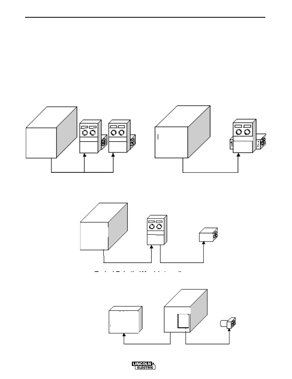
POWER WAVE
455M/STT (CE)
ROBOT
PLC CONTROLLER
ANALOG INTERFACE
etc.
POWER WAVE
455M/STT (CE)
POWER WAVE
455M/STT (CE)
POWER WAVE
455M/STT (CE)
FEED HEAD
SINGLE HEAD FEEDER
DUAL HEAD FEEDER
SINGLE HEAD BOOM FEEDER
FH 1
PF-10R
UP TO 4 FEEDERS
ALLOWED
UP TO 4 FEED HEADS
ALLOWED
WIRE
DRIVE
MODULE
Typical Robotic/ Hard Automation
(using Wire Drive Module and PF-10R)