Installation, Input connection, Input fuse and supply wire considerations – Lincoln Electric IM924 POWER WAVE 455M_STT User Manual
Page 13: Electrode and work cable connections, Caution, Warning
A-3
INSTALLATION
POWER WAVE 455M/STT (CE)
A-3
INPUT CONNECTION
Only a qualified electrician should connect the
input leads to the Power Wave 455M/STT (CE).
Connections should be made in accordance with
all local and national electrical codes and the con-
nection diagram located on the inside of the
reconnect/input access door of the machine.
Failure to do so may result in bodily injury or death.
-------------------------------------------------------------
Use a three-phase supply line. A 45 mm (1.75 inch)
diameter access hole for the input supply is located on
the upper left case back next to the input access door.
Connect L1, L2, L3 and ground according to the Input
Supply Connection Diagram decal located on the
inside of the input access door or refer to Figure A.1.
INPUT FUSE AND SUPPLY WIRE
CONSIDERATIONS
Refer to the Technical Specifications at the beginning
of this Installation section for recommended fuse and
wire sizes.
Fuse the input circuit with the recommend-
ed super lag fuse or delay type breakers (also called
“inverse time” or “thermal/magnetic” circuit breakers).
Choose an input and grounding wire size according to
local or national electrical codes. Using fuses or circuit
breakers smaller than recommended may result in
“nuisance” shut-offs from welder inrush currents, even
if the machine is not being used at high currents.
NOTE: Turn main input power to the machine OFF before performing connection procedure. Failure to do
so will result in damage to the machine.
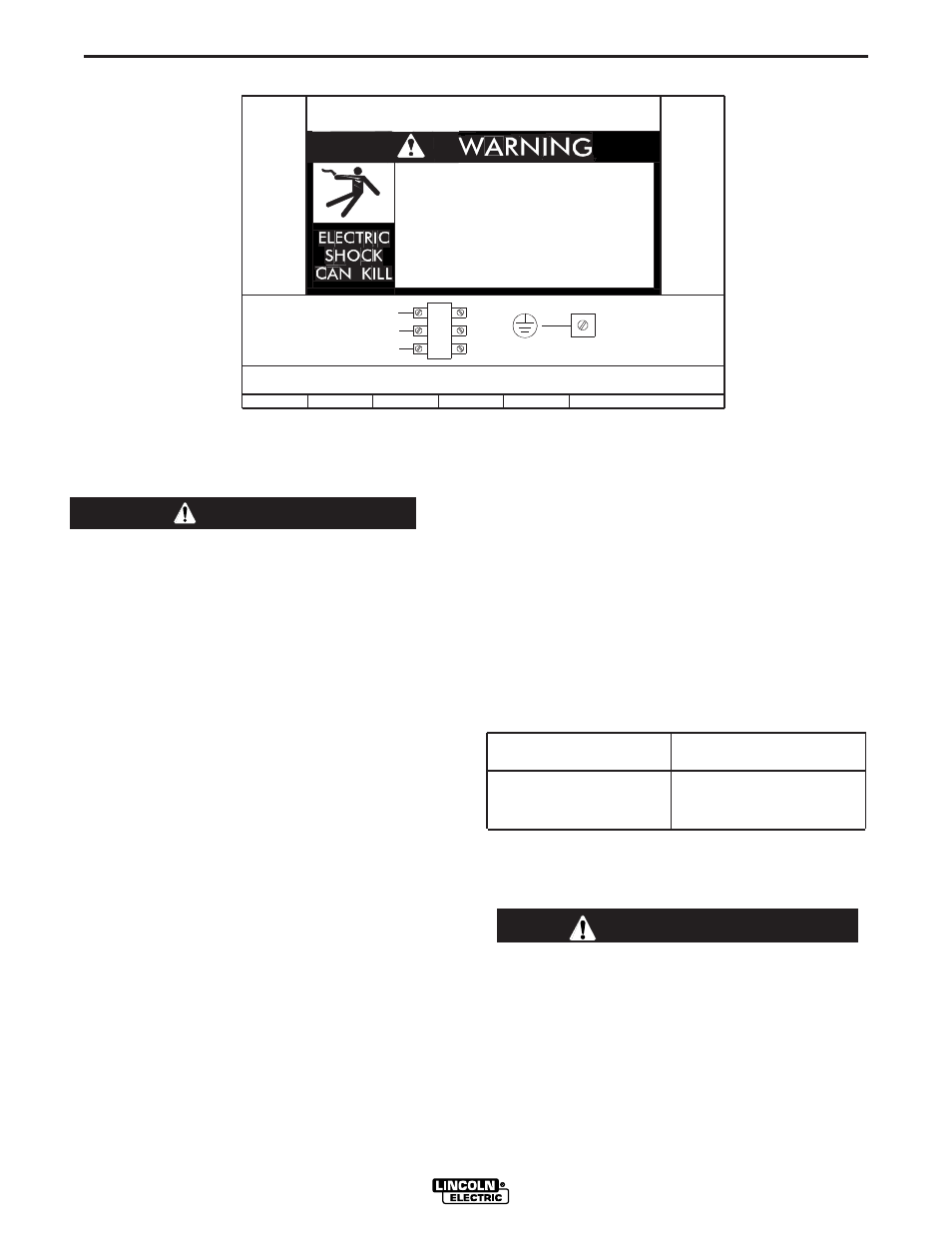
FIGURE A.1 - CONNECTION DIAGRAM ON CONNECTION/INPUT ACCESS DOOR
ELECTRODE AND WORK CABLE
CONNECTIONS
Connect a work lead of sufficient size and length (Per
Table 1) between the proper output terminal on the power
source and the work. Be sure the connection to the work
makes tight metal-to-metal electrical contact. To avoid
interference problems with other equipment and to
achieve the best possible operation, route all cables
directly to the work and wire feeder. Avoid excessive
lengths and do not coil excess cable.
Minimum work and electrode cables sizes are as follows:
TABLE A.1
Current (60% Duty Cycle) MINIMUM COPPER
WORK CABLE SIZE AWG
Up To-30 m Length (100 Ft.)
400 Amps
67 mm
2
(2/0)
500 Amps
85 mm
2
(3/0)
600 Amps
85 mm
2
(3/0)
NOTE: K1796 coaxial welding cable is recommended to
reduce the cable inductance in long cable lengths. This is
especially important in Pulse and STT applications.
When using inverter type power sources like the
Power Waves, use the largest welding (electrode and
ground) cables that are practical. At least 67 mm
2
(2/0) copper wire - even if the average output current
would not normally require it. When pulsing, the
pulse current can reach very high levels. Voltage
drops can become excessive, leading to poor welding
characteristics, if undersized welding cables are
used.
------------------------------------------------------------------------
CAUTION
W / L3
V / L2
U / L1
THE LINCOLN ELECTRIC CO. CLEVELAND, OHIO U.S.A.
XA
S24190
use or service this equipment.
Do not touch electrically live parts.
removed.
Only qualified persons should install,
Do not operate with covers
inspecting or servicing machine.
Disconnect input power before
.
.
.
.
CR1
INPUT SUPPLY CONNECTION DIAGRAM
WARNING