Installation – Lincoln Electric IM691 POWER WAVE 455R (CE) User Manual
Page 16
A-9
INSTALLATION
POWER WAVE 455/R (CE)
A-9
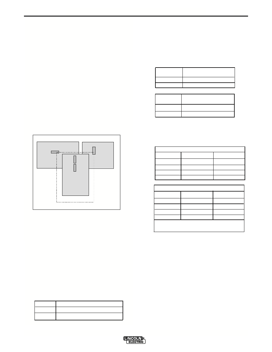
DIP SWITCH SETTINGS AND LOCATIONS
DIP switches on the P.C. Boards allow for custom
configuration of the Power Wave. To access the DIP
switches:
•
Turn off power at the disconnect switch.
•
Remove the top four screws securing the front
access panel.
•
Loosen, but do not completely remove, the bottom
two screws holding the access panel.
•
Open the access panel, allowing the weight of the
panel to be carried by the bottom two screws. Make
sure to prevent the weight of the access panel from
hanging on the harness.
•
Adjust the DIP switches as necessary.
•
Replace the panel and screws, and restore power.
CONTROL BOARD DIP SWITCH:
switch 1 = reserved for future use
switch 2 = reserved for future use
switch 3 = reserved for future use
switch 4 = reserved for future use
switch 5 = reserved for future use
switch 6 = reserved for future use
switch 7 = reserved for future use
switch 8 = work sense lead
switch 8
work sense lead
off work sense lead not connected
on work sense lead connected
FEED HEAD BOARD DIP SWITCH:
switch 1 = reserved for future use
switch 2 = reserved for future use
switch 3 = reserved for future use
switch 4 = reserved for future use
switch 5 = reserved for future use
switch 6 = reserved for future use
switch 7 = negative polarity switch
switch 7
electrode polarity
off
positive
on
negative
switch 8 = high speed gear
switch 8
wire drive gear
off
low speed gear
on
high speed gear
DEVICENET/GATEWAY BOARD DIP SWITCH,BANK
(S2):
switch 1,2 = configure the baud rate for DeviceNET
Prior to S24958-6 software
switch 1
switch 2 baud rate
off off
-------
on
off
125K
off
on
250K
on on 500
S24958-6 and later software
switch 1 switch 2 baud rate
off off
125K
off
on
250K
on
off
500K
on on 500K
programmable value. Consult local Lincoln
Technical representative
switch 5 = reserved for future use
switch 6 = reserved for future use
switch 7 = reserved for future use
switch 8 = reserved for future use
Feed Head Board
Control Board
DeviceNet/Gateway Board
Left
Right
Bank S1
Bank S2