Installation, Single head boom feeder, A-5 configuring the system – Lincoln Electric IM846 POWER WAVE 405M User Manual
Page 14: Pf-10r
A-5
INSTALLATION
POWER WAVE
®
405M
A-5
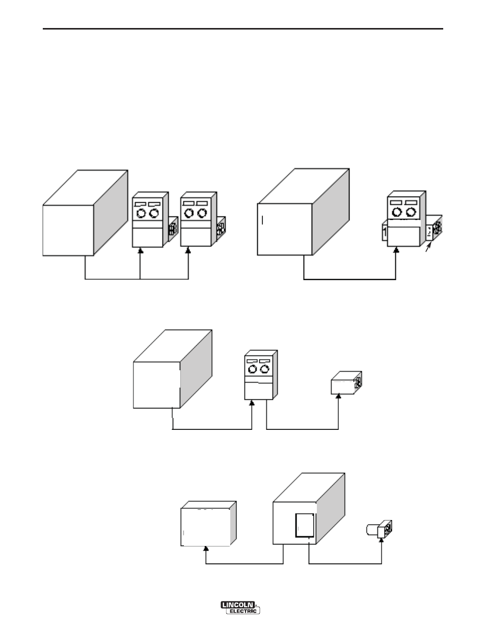
CONFIGURING THE SYSTEM
The power source will “Auto Map” the system eliminat-
ing most of the need to set DIP switches to configure
the system.
If a system can not be “Auto Mapped” then the status
light on the power source will blink green fast and the
welder output will be disabled.
If a system can not be “Auto Mapped” then the status
light on the power source will blink green fast and the
welder output will be disabled. If a system is not
“Auto-mappable”, then consult the instruction manual
for the accessory being used for configuration infor-
mation about DIP switch settings, or consult your local
Lincoln sales representative.
POWER WAVE
®
405M
ROBOT
PLC CONTROLLER
ANALOG INTERFACE
etc.
POWER WAVE
®
405M
POWER
WAVE
®
POWER WAVE
®
405M
FEED HEAD
FEED HEAD 1
CONTROL BOX
SINGLE HEAD FEEDER
DUAL HEAD FEEDER
SINGLE HEAD BOOM FEEDER
PF-10R
SINGLE HEAD BOOM FEEDER
UP TO 4 WIRE FEEDERS
ALLOWED
UP TO 4 FEED HEADS
ALLOWED
WIRE
DRIVE
MODULE
- Invertec V310-T DC (2 pages)
- VANTAGE 500 (CE) 11575 (50 pages)
- INVERTEC V350-PRO SVM152-A (155 pages)
- IMVERTEC V160-T (36 pages)
- IDEALARC CV-300 (112 pages)
- INVERTEC POWER WAVE 450 SVM112-B (293 pages)
- AUTO-DARKENING HELMET IM10001 (12 pages)
- IM10111 IDEALARC R3R-500-I (28 pages)
- IM10110 IDEALARC R3R-400 (25 pages)
- IM10051 INVERTEC V311-T AC_DC (38 pages)
- IM10059 SQUARE WAVE TIG 175 (30 pages)
- IM10096 POWER MIG 256 (37 pages)
- IM10096 POWER MIG 256 (38 pages)
- IM10105 POWER MIG 350MP (47 pages)
- IM10115 FLEXTEC 650 (42 pages)
- IM10132 FLEXTEC 650 (56 pages)
- IM10132 FLEXTEC 650 (36 pages)
- IM10018 IDEALARC DC-600 VRD (55 pages)
- IM10107 IDEALARC DC-400 (40 pages)
- IM10062 FLEXTEC 450 (72 pages)
- IM10091 FLEXTEC 450 CE (40 pages)
- IM10094 RED-D-ARC FX450 (31 pages)
- IM10157 12_24V 10A Auto HF Household Charger (16 pages)
- IM10139 JUMP STARTER (12 pages)
- IM10149 POWER WAVE ADVANCED MODULE (46 pages)
- IM10102 AIR VANTAGE 650 (60 pages)
- IM10103 AIR VANTAGE 700 (AU) (57 pages)
- IM10065 AIR VANTAGE 500 CUMMINS (54 pages)
- IM10066 AIR VANTAGE 500 (AU) (56 pages)
- IM10041 VANTAGE 500 CUMMINS (56 pages)
- IM10128 AIR VANTAGE 500 KUBOTA (AU) (56 pages)
- IM10090 ARC TRACKER (48 pages)
- IM10147 AUTO-DARKENING HELMET (12 pages)
- IM10087 AutoDrive 19 CONTROLLER (28 pages)
- IM10125 AutoDrive 19 TANDEM (34 pages)
- IM10069 AutoDrive 4R100 (32 pages)
- IM10145 AUTOPRO 20 (24 pages)
- IM10025 BIG RED 500 (40 pages)
- IM10019 BIG RED 600 (41 pages)
- IM10005 BULLDOG 140 (46 pages)
- IM10074 BULLDOG 5500 (56 pages)
- IM10067 CENTURY AC120 (20 pages)
- IM10109 CIRCULATOR (33 pages)
- IM10109 CIRCULATOR (36 pages)
- IM10153 CLASSIC 300 HE (60 pages)