Installation, Warning – Lincoln Electric IM777 POWER FEED 10M Dual WIRE FEEDER User Manual
Page 14
A-6
INSTALLATION
POWER FEED
®
10M DUAL WIRE FEEDER
A-6
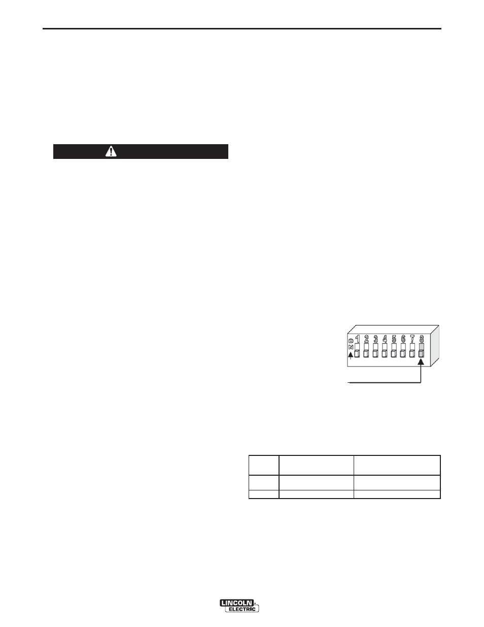
GEAR RATIO RECOGNITION:
1. Remove the rear access door from the wire feeder
case.
2. Locate the dip switch bank on the P.C. board (refer
to table A.3)
3. Locate dip switch # 8 and move it to the appropriate
gear ratio setting as described below:
FIGURE A.2
sw1
UP - High Speed Gear Ratio
DOWN - Low Speed Gear Ratio
4. Replace the rear access door of the wire feeder
case.
Note: The system recognizes dip switch settings only
during system power-up.
TABLE A.3
PF-10M Feeder location PF-10M P.C. board location
(Facing rear of unit)
(Facing rear of unit)
Feeder 1
Right
On inside divider panel
Feeder 2
Left
On rear access door
}
5. Remove the small gear from the output shaft.
Lightly cover the output shaft with engine oil or
equivalent. Install gear onto output shaft and
secure with flat washer, lock washer, and Phillips
head screw which were previously removed.
6. Tighten the screw on lower right face of feed plate.
7. Re-attach feed plate to wire feeder if removed in
Step 2.
8. Feed plate will be rotated out-of-position due to
the gear change. Adjust the angle of the feed plate
per the instructions above.
9. Set the wire drive gear ratio switch on Wire Drive
PC board as follows:
CHANGING THE WIRE DRIVE GEAR RATIO
Changing the ratio requires a gear and a dip switch
setting change. The Power Feed
®
Wire Feeders are
shipped with both high speed and a low speed gears.
As shipped from the factory, the low speed (high
torque) gear is installed on the feeder. For identifica-
tion purposes, the low speed (high torque) gear has
20 teeth and is 1.1 inches in diameter. The high speed
gear has 30 teeth and is 1.6 inches in diameter.
Power down the Power Feed
®
10M Dual Wire
Feeder by turning off its companion Power Wave
power source. For maximum safety, disconnect
the control cable from the Power Feed
®
10M Dual
Wire Feeder.
-----------------------------------------------------------
GEAR RATIO CHANGE PROCEDURE:
1. Pull open the Wire Drive Door.
2. Remove the Phillips head screw retaining the pin-
ion gear to be changed and remove the gear. If
the gear is not easily accessible or difficult to
remove, remove the feed plate from the gearbox.
To remove feed plate:
a. Loosen the clamping collar screw using a
3/16" Allen wrench. The clamping collar screw
is accessed from the bottom of the feed plate.
It is the screw which is perpendicular to the
feeding direction.
b. Loosen the retaining screw, which is also
accessed from bottom of feeder, using a 3/16"
Allen wrench. Continue to loosen the screw
until the feed plate can be easily pulled off of
the wire feeder.
3. Loosen, but do not remove, the screw on the
lower right face of the feed plate with a 3/16" Allen
wrench.
4. Remove the screw on the left face of the feed
plate. If changing from high speed (larger gear) to
low speed (smaller gear), line the lower hole on
the left face of the feed plate with the threads on
the clamping collar. Line the upper hole with the
threads to install larger gear for high speed feeder.
If feed plate does not rotate to allow holes to line
up, further loosen the screw on right face of feed
plate.
WARNING