Installation, Installing the lamp kit, Fig. 2 – Lincoln Electric IM627 Lamp Kit for Wall-Mounted Systems User Manual
Page 10: Fig. 3, Fig. 4, Fig. 5
LAMP KIT FOR WALL-MOUNTED SYSTEMS
A-3
INSTALLATION
A-3
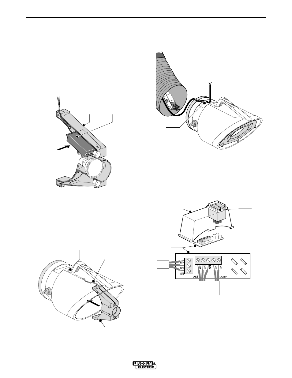
INSTALLING THE LAMP KIT
INSTALLING THE AUTO START/STOP SENSOR
If not installing the Auto start/stop arc sensor,
skip to the next step (Figure 3).
Use a small phillips-head screwdriver to remove the
six screws that hold the lamp housing (Fig. 2A)
together. Insert the sensor (Fig. 2B) as shown. Route
the leads through the lamp housing and out with the
lamp leads as shown in Figure 2. Reclose the lamp
housing using the six screws.
INSTALLING THE LAMP IN THE HOOD
Feed the lamp and/or sensor cable(s) (Fig. 3B)
through the hole (Fig. 3A) in the top of the hood, and
snap the lamp holder (Fig. 3C) into place, top end
first. Remount the airflow focus vanes in the open end
of the hood.
B
A
Fig. 2
A
B
C
Fig. 3
INSTALLING THE SWITCH BOX AND
MAKING CONNECTIONS
Feed the 36 ft. connecting cable through the hole in
the hood (Fig. 4B).
Have a qualified electrician connect the 36 ft. connect-
ing cable, lamp cable, and sensor cable (if used) to
the control board as shown in Figure 5. Snap the
board onto the bottom of the remote switch. Snap the
switch box into the hood by squeezing the front and
back.
B
Fig. 4
WH
BN
GN
IMS
LAMP
WH
BN
GN
BK
BK
A
B
C
TO: Auto
Sensor
TO:
Lamp
TO:
Control
Box
Fig. 5