Installation, Mounting products supported, Warning – Lincoln Electric IM512 INVERTEC RACKS User Manual
Page 11: Electrical installation, K912 series of steel racks (8), Mounting k900-1 dc tig starter, Input connection
- 4 -
INVERTEC RACKS
INSTALLATION
K912 Series of Steel Racks (8)
Step 1 Unpack Carton
Remove eight pack carton. Hoist rack 1 ft. above
ground level to remove pallet from rack. With rack on
level surface, remove screws that fasten hood down.
For racks with main disconnect, the switch must be in
the
“
OFF
”
position before the hood can be removed.
Remove hood from rack and take out parts bag and
check against the list provided. K912 series of racks
come with skids and do not require any assembly.
The rack is ready for mounting products supported.
MOUNTING PRODUCTS SUPPORTED
Always check for proper and secure mounting of
equipment before hoisting the rack to high or low ele-
vations.
------------------------------------------------------------------------
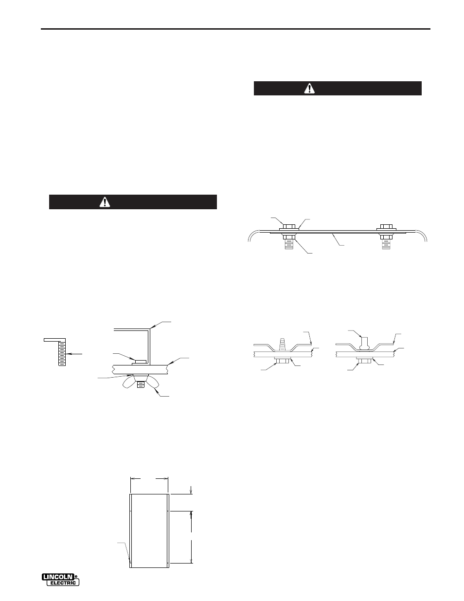
Mounting Power Source
Place power source in rack with controls toward the
front of rack. Align unit with mounting holes. Insert
four #10-24 x .75
”
L-bolts from the top side and
secure each L-bolt as follows:
Mounting K900-1 DC TIG Starter
The Invertec power source handles must be removed
in order to slide the Invertec/TIG unit into the rack.
Follow safety instructions and capacitor discharge
procedure as outlined in owner
’
s manual before ser-
vicing inverter power source.
------------------------------------------------------------------------
Remove handles from Invertec case. Use handle
hardware and flange nuts provided with rack to plug
the holes in the Invertec case, as shown below. A
quantity of eight and sixteen 3/8
”
flange nuts are sup-
plied with four pack and eight pack racks respectively.
Note: Earlier code machines may have insulation
held in place by handle hardware. If so, do not
remove it.
WARNING
L-BOLT
POWER SOURCE
BASE
RACK
SHELF
WING NUT
WASHER
Note:
Earlier code power sources may not have all four or
any mounting holes on the bottom of the base. If
hoisting the rack to high or low elevations is required,
provisions for the use of all four mounting screws
must be made. Use the following dimensions for hole
locations.
4 . 5 0
9 . 6 5
1 3 . 5 0
BACK
BOTTOM
VIEW
FRONT
.22 DIA
(4 PLACES)
WARNING
S C R E W
W A S H E R
F L A N G E N U T
I N S U L A T I O N
( I F P R E S E N T )
Once the handles are removed, follow the instructions
in the TIG Starter Owner
’
s Manual to mount the
Invertec on top of the DC TIG Starter.
Place the Invertec/TIG unit into the rack with controls
toward front of rack. Align unit with mounting holes.
Secure Invertec/TIG unit to shelf as follows:
SCREW
WASHER
RACK
SHELF
TIG BASE
W/O RIVNUTS
RIVNUT
TIG BASE
W/O RIVNUTS
RACK
SHELF
WASHER
#10-32
SCREW
ELECTRICAL INSTALLATION
Racks should be connected only by a qualified electri-
cian. Installation should be made in accordance with
the U.S. National Electrical Code, all local codes and
the information detailed below:
Input Connection
A 2.88
”
hole is provided for input lines for low voltage
operation (208/230V). All racks except K898-3, -4 are
provided with reducing washers for input lines for high
voltage operation (460/575V). Strain relief connectors
for input cables are not supplied with racks. Make sure
connections are secure and water tight. Ground lead
for rack must accompany input lines.